5 Electrical installation
Installation manual
23
EGSAH/X06+10UDA9W
Daikin Altherma 3 GEO
4P598591-1A – 2019.12
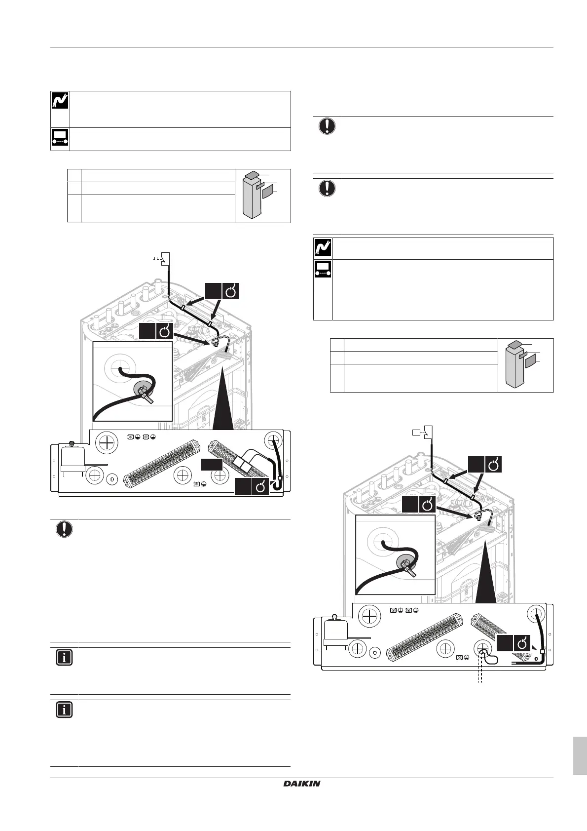
5.12 To connect the safety thermostat
(normally closed contact)
Wires: 2×0.75mm²
Safety thermostat contact: 16VDC detection (voltage
supplied by PCB)
[9.8.1]=3 (Benefit kWh power supply = Safety
thermostat)
1 Open the following (see "3.2.1To open the indoor unit"[47]):
1 Top panel
2 User interface panel
3 Installer switch box cover
2 Connect the safety thermostat (normally closed) cable to the
appropriate terminals as shown in the illustration below.
3 Fix the cable with cable ties to the cable tie mountings.
NOTICE
Make sure to select and install the safety thermostat
according to the applicable legislation.
In any case, to prevent unnecessary tripping of the safety
thermostat, we recommend the following:
▪ The safety thermostat is automatically resettable.
▪ The safety thermostat has a maximum temperature
variation rate of 2°C/min.
▪ There is a minimum distance of 2m between the safety
thermostat and the 3‑way valve.
INFORMATION
ALWAYS configure the safety thermostat after its
installation. Without configuration, the indoor unit will
ignore the safety thermostat contact.
INFORMATION
The preferential kWh rate power supply contact is
connected to the same terminals (X5M/9+10) as the safety
thermostat. Thus, the system can have EITHER
preferential kWh rate power supply OR a safety
thermostat.
5.13 To connect the brine low pressure
switch
Depending on the applicable legislation, you might have to install a
brine low pressure switch (field supply).
NOTICE
Mechanical. We recommend to use a mechanical brine
low pressure switch. If an electrical brine low pressure
switch is used, capacitive currents might disturb the flow
switch operation causing an error on the unit.
NOTICE
Before disconnecting. If you want to remove or
disconnect the brine low pressure switch, first set [C‑0B]=0
(brine low pressure switch not installed). If not, this causes
an error.
Wires: 2×0.75mm²
Set overview field setting [C-0B]=1.
▪ If [C-0B]=0 (brine low pressure switch not installed), the unit
does not check the input.
▪ If [C-0B]=1 (brine low pressure switch installed), the unit
checks the input. If the input is "open", error EJ-01 occurs.
1 Open the following (see "3.2.1To open the indoor unit"[47]):
1 Top panel
2 User interface panel
3 Installer switch box cover
2 Connect the brine low pressure switch cable as shown in the
illustration below.
2×
1×
A16P/X13A/1+4
1×
S1PL
P<

 Loading...