5 Electrical installation
Installation manual
26
EGSAH/X06+10UDA9W
Daikin Altherma 3 GEO
4P598591-1A – 2019.12
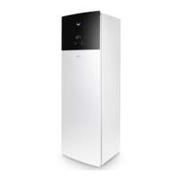
# Router connection
B Wireless
e Wireless bridge (field supply)
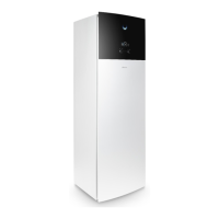
C Power line
f Power line adapter (field supply)
g Power line (field supply)
INFORMATION
It is recommended to connect the LAN adapter to the
router directly. Depending on the wireless bridge or power
line adapter model, the system might not function properly.
NOTICE
To prevent communication problems due to cable
breakdown, do NOT exceed the minimum bend radius of
the Ethernet cable.
5.15.4 Electricity meter
If the LAN adapter is connected to an electricity meter, make sure it
is an electrical pulse meter.
Requirements:
Item Specification
Type Pulse meter
(5VDC pulse
detection)
Possible number of pulses ▪ 100pulse/kWh
▪ 1000pulse/kWh
Pulse duration Minimum On
time
10ms
Minimum OFF
time
100ms
Measurement type Depends on the installation:
▪ 1N~AC meter
▪ 3N~ AC meter (balanced
loads)
▪ 3N~ AC meter (unbalanced
loads)
INFORMATION
It is required that the electricity meter has a pulse output
that can measure the total energy injected INTO the grid.
Suggested electricity meters
Phase ABB reference
1N~ 2CMA100152R1000 B21 212-100
3N~ 2CMA100166R1000 B23 212-100
To connect the electricity meter
NOTICE
To prevent damage to the PCB, it is NOT allowed to
connect the electrical wiring with the connectors already
connected to the PCB. First connect the wiring to the
connectors, then connect the connectors to the PCB.
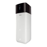
1 Open the following (see "3.2.1To open the indoor unit"[47]):
1 Top panel
2 User interface panel
3 Front panel
4 Main switch box cover
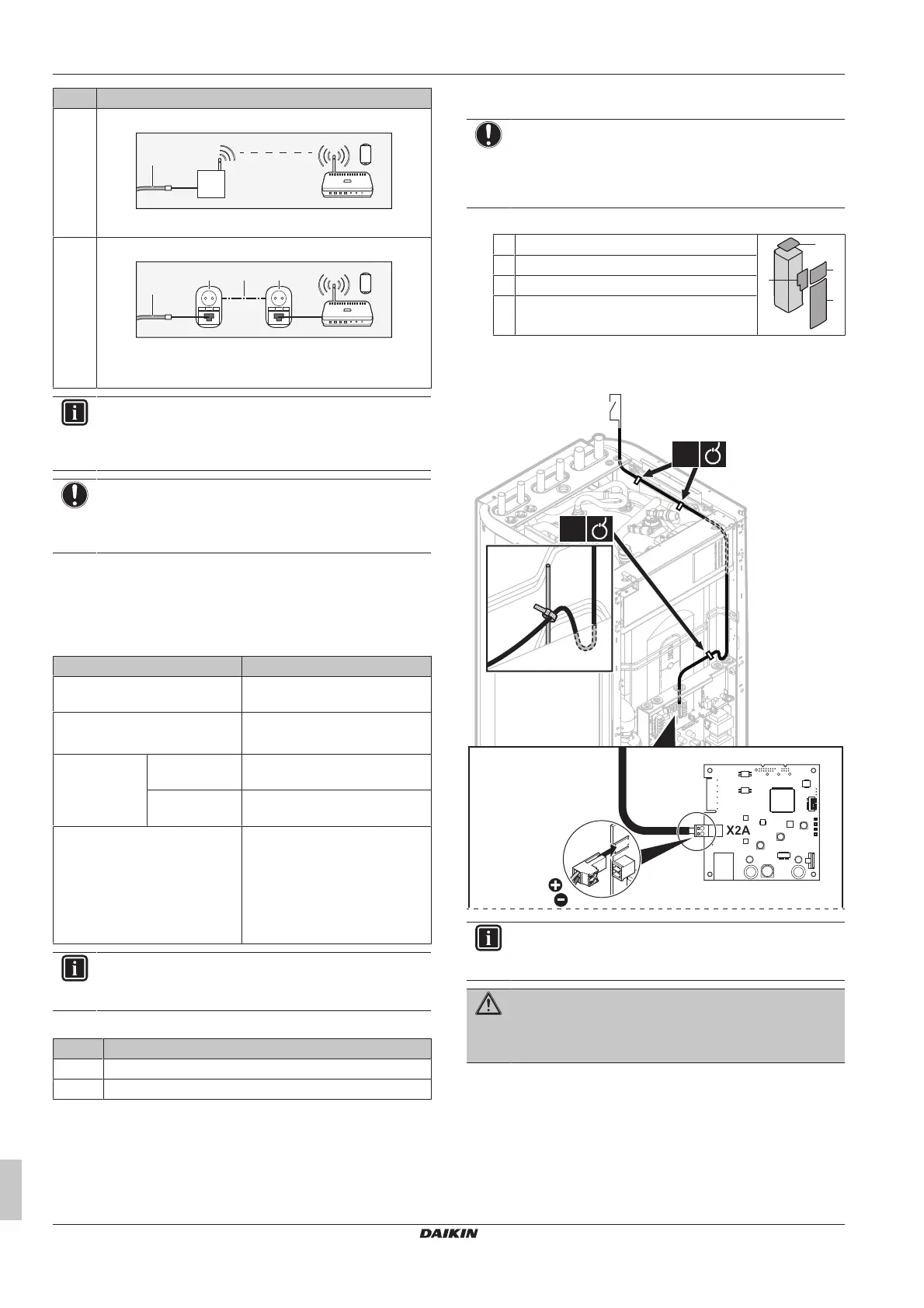
2 Connect the electricity meter to LAN adapter terminals
X2A/1+2.
INFORMATION
Mind the polarity of the cable. The positive wire MUST be
connected to X2A/1; the negative wire to X2A/2.
WARNING
Make sure to connect the electricity meter in the correct
direction, so that it measures the total energy injected
INTO the grid.

 Loading...