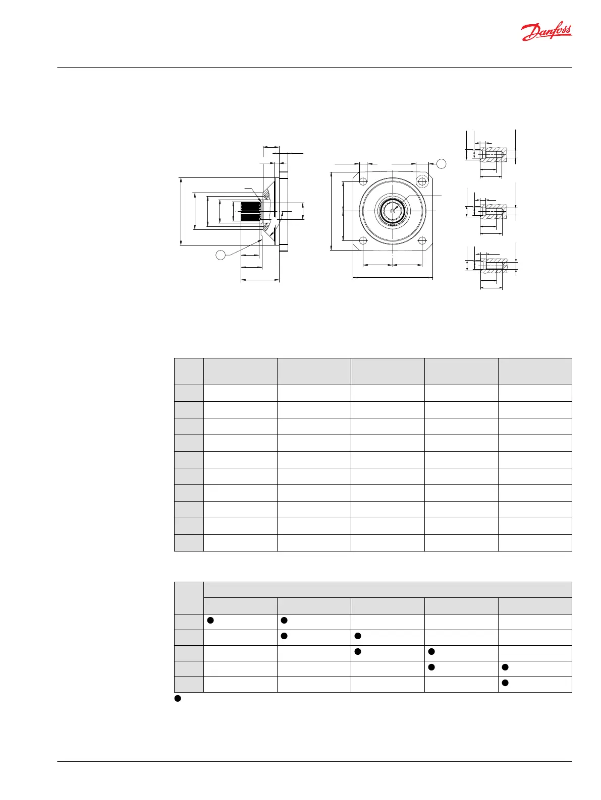
DIN mounting flange design per ISO 3019/2
ØA
ØJ
ØH
ØG
ØE
ØB
DB
DA
R
DJ
DH
DC
P003 441
45°
DK
DL
DLDL
DK
DL
(4x)
(4x)
DN
DM
V
DD
23
31
8
V (M10)
∅14.9
∅10.5
M10x1.5
29
38
10
V (M12)
∅18.1
∅13
M12x1.75
38
44
12.5
V (M16)
∅23
∅17
M16x2
1
2
1. Coupling must not protrude beyong this surface
2. Maximum screw head space other side
DIN mounting flange per ISO 3019/2 dimensions, mm [in]
Size 060
125 B4 HL
Size 080
140 B4 HL
Size 110
160 B4 HL
Size 160
180 B4 HL
Size 210
200 B4 HL
ØB
125.0 [4.921] 140.0 [5.512] 160.0 [6.299] 180.0 [7.087]
200.0 [7.874]
ØE
72.0 [2.835] 76.6 [3.016] 85.9 [3.382] 98.8 [3.890]
102.0 [4.016]
ØG
62.0 [2.441] 62.0 [2.441] 72.0 [2.835] 72.0 [2.835] 72.0 [2.835]
DD
30.0 [1.181] 31.2 [1.228] 39.0 [1.535] 38.8 [1.528] 38.9 [1.531]
DH
11.2 [0.441] 11.1 [0.437] 10.8 [0.425] 10.1 [0.398] 11.0 [0.433]
DJ
17.0 [0.669] 19.0 [0.748] 22.2 [0.874] 22.0 [0.866] 25 [0.984]
DK
150.0 [5.905] 165.0 [6.496] 190.0 [7.840] 212.0 [8.346] 236.0 [9.291]
DL
56.6 [2.228] 63.7 [2.509] 70.7 [2.783] 79.2 [3.118] 88.4 [3.480]
DM
19.5 [0.768] 19.5 [0.768] 30.0 [1.181] 30.0 [1.181] 37.0 [1.457]
DN
13.5 [0.531] 13.5 [0.531] 17.5 [0.689] 17.5 [0.689] 22 [0.866]
Shaft options overview
Size Shaft option (Number of teeth)
GN/GS (14T) HN/HS (16T) JN/JS (18T) KN/KS (21T) LN/LS (24T)
060
— — —
080
— —
110
— — —
160
— — —
210
— — — —
= available option, – = not available option
Technical Information
H1 Bent Axis Variable Displacement Motors, Size 060/080/110/160/210/250
Dimensions
©
Danfoss | December 2016 11037153 | BC00000043en-US1103 | 107
 Loading...