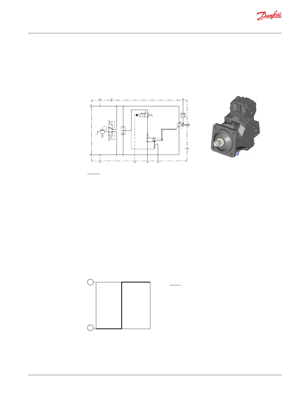
Option HFHF – hydraulic two-position control
HF – hydraulic two-position control, non-pressurized = minimum displacement / external control
pressure supply
HF – without PCOR / without BPD, internal servo pressure supply
Hydraulic schematic
B
A
n
N
M4 M5
L2
L1
max
min
MA
MB
P301 322
X1
Where:
A, B Main pressure lines
L1, L2 Drain lines
M4, M5 Gauge port servo pressure
MA, MB Gauge port system pressure
N Speed sensor (optional)
Option HFHF
Control pressure X1
Non-pressurized = Minimum displacement.
Pressurized = Maximum displacement.
Control pressure > 12 bar [174 psi] to ensure maximum displacement (above case pressure)
Control pressure < 0.9 bar [13 psi] to ensure minimum displacement (above case pressure)
Maximum control pressure: 100 bar [1450 psi]
Displacement versus control signal
P301 332
12 bar [174 psi]
2
1
Where:
1 Maximum displacement
2 Minimum displacement
Technical Information
H1 Bent Axis Variable Displacement Motors, Size 060/080/110/160/210/250
Controls – nomenclature, description
©
Danfoss | December 2016 11037153 | BC00000043en-US1103 | 81
 Loading...