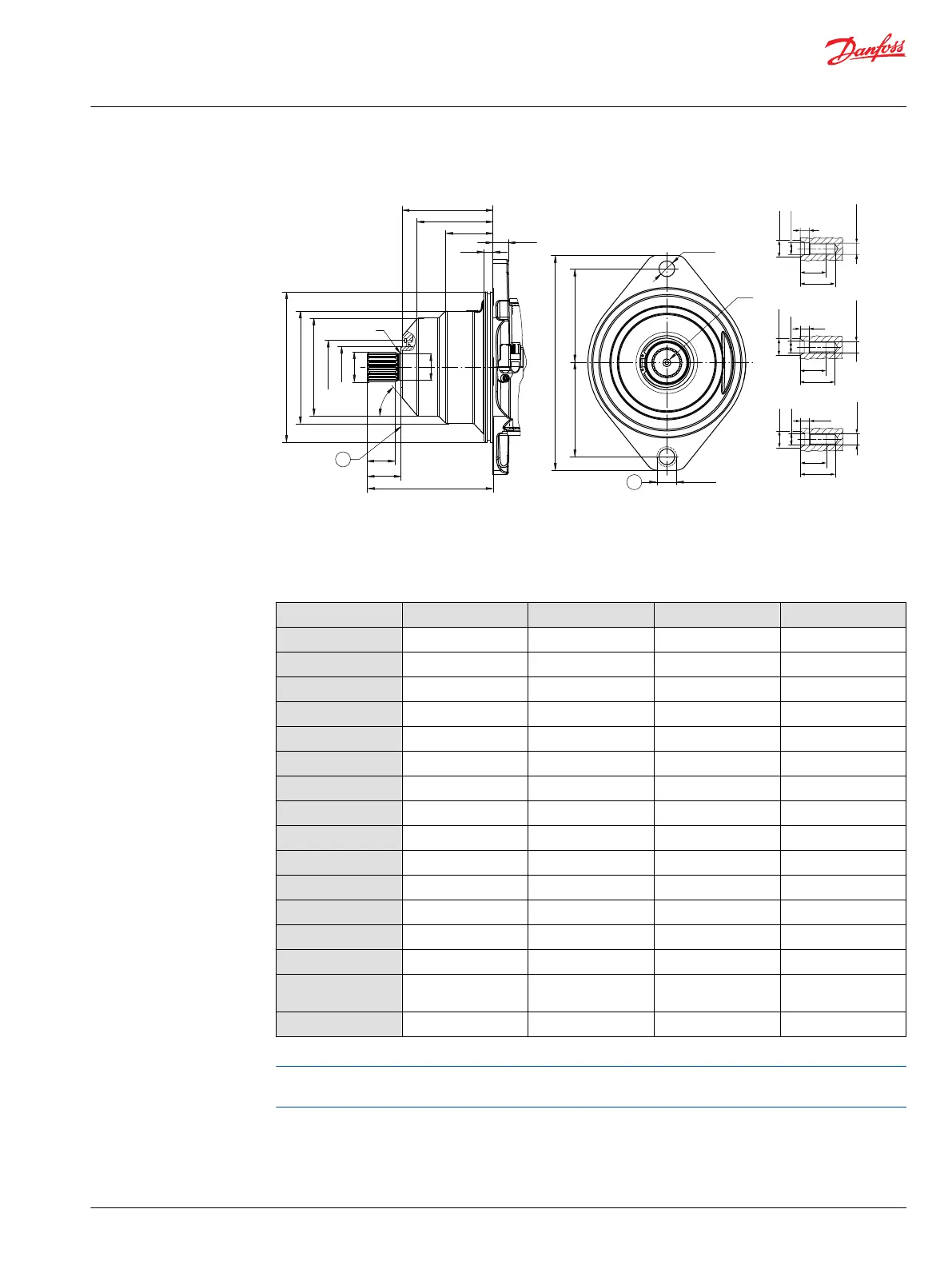
Cartridge mounting flange design
ØA
ØJ
ØD
ØH
ØG
ØC
ØB
DC
DG
DH
DJ
DF
DD
DB
DA
P003 449
(2x)
(2x)
DN
DK
DL DL
DM
R
DE
V
23
31
8
V (M10)
∅14.9
∅10.5
M10x1.5
29
38
10
V (M12)
∅18.1
∅13
M12x1.75
38
44
12.5
V (M16)
∅23
∅17
M16x2
1
2
1. Coupling must not protrude beyong this surface
2. Maximum screw head space other side
Cartridge flange dimensions, mm [in]
Measure Size 060 Size 080 Size 110 Size 160
ØB
160 [6.299] 190 [7.480] 200 [7.874] 200.0 [7.874]
ØC
121.0 [4.764] 134.0 [5.276] 150.0 [5.905] 170.0 [6.693]
ØD
104.0 [4.094] 116.0 [4.567] 130.0 [5.118] 146.0 [5.748]
ØG
62.0 [2.441] 62.0 [2.441] 72.0 [2.835] 72.0 [2.835]
DE
53° 54° 40° 45°
DD
90.4 [3.559] 109.2 [4.299] 121.0 [4.764] 121.0 [4.772]
DF
71.1 [2.799] 80.9 [3.185] 101.8 [4.008] 98.0 [3.858]
DG
40.7 [1.602] 56.6 [2.228] 63.8 [2.512] 61.5 [2.423]
DH
12.6 [0.496] 11.2 [0.441] 11.2 [0.441] 11.2 [0.441]
DJ
16.2 [0.638] 18.0 [0.709] 20.1 [0.791] 20.0 [0.787]
DK
235.0 [9.252] 260.0 [10.236] 286.0 [11.260] 286.0 [11.260]
DL
100.0 [3.937] 112.0 [4.409] 125.0 [4.921] 125.0 [4.921]
DM
30.0 [1.181] 30.0 [1.181] 30.0 [1.181] 30.0 [1.181]
DN
17.0 [0.669] 21.0 [0.827] 21.0 [0.827] 21.0 [0.827]
O-Ring
*
3.0 x 150.0
[0.12 x 5.91]
3.0 x 179.0
[0.12 x 7.047]
3.0 x 192.0
[0.12 x 7.559]
3.0 x 192.0
[0.12 x 7.559]
Material Nr.
726927 502205 502206 502206
*
O-Ring is not part of the shipment.
Motor installations will vary by application. It is the customer’s responsibility to evaluate each application
for proper mounting and sealing.
Technical Information
H1 Bent Axis Variable Displacement Motors, Size 060/080/110/160/210/250
Dimensions
©
Danfoss | December 2016 11037153 | BC00000043en-US1103 | 117
 Loading...