6-4
VLT is a registered Danfoss trademark
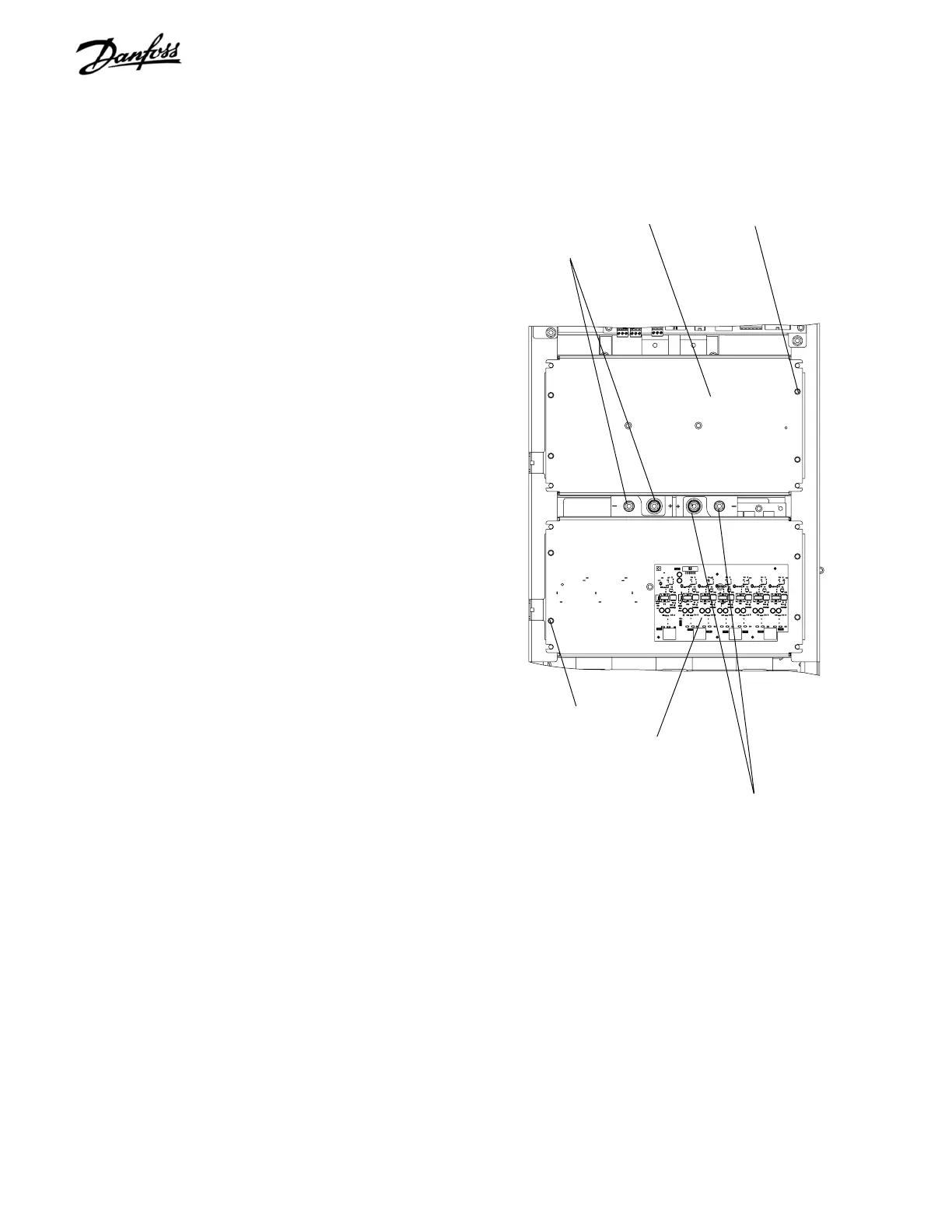
6.7 Capacitor Bank(s)
NOTE
D2 size units have 2 capacitor bank assemblies
mounted one above the other. Separate
disassembly instructions are given for upper and
lower capacitor banks. For D1 units with one
capacitor bank assembly only, disassemble in
accordance with instructions for single capacitor
bank units 6.7.3.
6.7.1 Upper Capacitor Bank D2 Units
1. Remove control card cassette in accordance with
instructions.
2. Capacitor bank connection to DC bus bars can
be seen recessed in the gap between upper and
lower cap banks. Remove left most 2 nuts
(10mm) from DC bus bars. A minimum 4 in.
(100mm) extension is required.
3. Remove 4 retaining nuts (10 mm) from cap bank
cover plate and remove cover plate.
4. Note that weight of cap bank is approx. 20 lbs. (9
kg). Remove cap bank by pulling free from
mounting studs.
Reinstall in reverse order of this procedure. Tighten mounting
screws to 35 in-lbs (4 Nm).
6.7.2 Lower Capacitor Bank D2 Units
1. Capacitor bank connection to DC bus bars can
be seen recessed in the gap between upper and
lower cap banks. Remove right most 2 cap bank
retaining nuts (10mm) from DC bus bars. A
minimum 4 in. (100mm) extension is required.
2. Disconnect MK102, MK103, MK104, and MK106
from gate drive card. Also remove MK105, for
units with brake, and MK101 for units with RFI
filter. Note that IGBT gate drive card can remain
attached to cap bank cover plate.
3. Remove 4 retaining nuts (10mm) from cap bank
cover plate and remove plate.
4. Note that weight of cap bank is approx. 20 lbs. (9
kg). Remove cap bank by pulling free from
mounting studs.
Reinstall in reverse order of this procedure. Tighten mounting
screws to 35 in-lbs (4 Nm).
Upper cover plate
retaining nut
Lower cover plate
retaining nut
Upper cap bank assy
retaining nuts
Lower cap bank assy
retaining nuts
Figure 6-5. D2 Upper and Lower Capacitor Bank
Assemblies
Gate drive card
Upper cover plate
 Loading...
