5-25
VLT is a registered Danfoss trademark
5.2.12 Current Sensors Test
The current sensors are Hall effect devices that send a signal
proportional to the actual output current waveform to the power
card. The current scaling card, attached to the power card,
scales the signals from the current sensors to the proper level
for monitoring and processing motor control data. A defective
current sensor can cause erroneous ground faults and over
current trips. In such instances, the fault will usually only occur
at higher loads. If the incorrect current scaling card is installed,
the current signals will be improperly scaled. This could cause
erroneous over current trips. If the current scaling card is not
installed, the drive will trip.
A couple of simple checks can be made to determine the
status of the sensors.
1. Apply power to drive.
2. Ensure that motor check, pre-magnetizing, DC
hold, DC brake, or other parameter setups are
disabled that create a holding torque while at
zero speed. Current displayed will exceed 1 to 2
amps if such parameters are not disabled.
3. Run drive with a zero speed reference. Note
output current reading in display. Display should
indicate approximately 1 to 2 amps.
If the current is greater than 1 to 2 amps and a current
producing parameter is not active, the test will need to be
made again with the motor leads disconnected.
4. Remove power from drive. Monitor DC bus
voltage at power card connector MK105 (A) and
(B) to ensure bus is fully discharged.
5. Remove output motor leads from terminals U, V,
and W.
6. Apply power to drive.
7. Run drive with a zero speed reference. Note
output current reading in display. Display should
indicate less than 1 amp.
If an incorrect reading was obtained from the above tests,
further tests of the current feedback signals are required using
the signal test board.
Testing current feedback with the signal test board.
8. Remove power to drive. Ensure DC bus is fully
discharged.
9. Install signal test board into interface card
connector MK104.
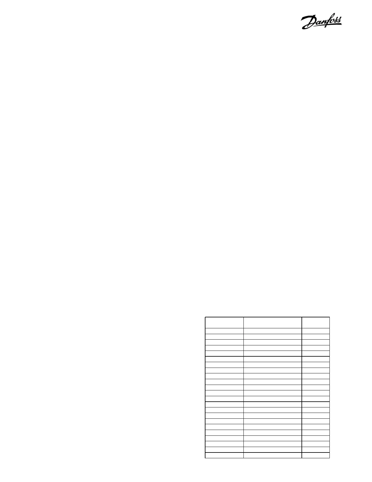
10. Using a DVM, measure resistance between
terminals 1 and 4, 2 and 4, and 3 and 4 of signal
test board. Resistance should be the same for
all three readings. Table 5-2 shows approximate
resistance readings based on drive power and
voltage rating. Note that values listed are values
at the current scaling card. When measuring
with signal test board, actual reading may be
higher due to meter lead resistance. Absence of
resistance indicates a missing scaling card.
11. Reapply power to drive.
12. Using a DVM, connect negative (-) meter lead
to terminal 4 (common) of signal test board.
13. Run drive with a zero speed reference.
14. In turn measure AC voltage at terminals 1, 2,
and 3 of signal test board. These terminals
correspond with current sensor outputs U, V,
and W, respectively. Expect a reading near
zero volts but no greater than 15mv.
If the control card parameters are setup to provide holding
torque while at zero speed, the current displayed will be greater
than expected. To make this test disable such parameters.
The current sensor feedback signal at this point in the circuit
will read approximately 400mv at 100% drive load so any reading
above 15mv while the drive is at zero speed has a negative
effect on the way the drive interprets the feedback signal.
A reading of greater than 15mv suggests that the corresponding
current sensor be replaced. See the disassembly instructions
in Section 6 or 7.
Table 5-2. Scaling Card Resistance Values
Voltage (VAC) Drive Model Number Resistance
(Ohms)
380-500 5122, 4152, 6152, 8152 4.5
380-500 5152, 4202, 6172, 8202 3.8
380-500 5202, 4252, 6222, 8252 3.1
380-500 5252, 4302, 6272, 8302 2.6
380-500 5302, 4352, 6352, 8352 5.1
380-500 5352, 4452, 6402, 8452 4.2
380-500 5452, 4502, 6502, 8502 2.6
380-500 5502, 4602, 6552, 8602 2.6
380-500 5552, 4652, 6602, 8652 2.6
525-600/690 5042, 8052 5.9
525-600/690 5052, 8062 5.9
525-600/690 5062, 8072 5.9
525-600/690 5072, 4102, 6102, 8102 5.9
525-600/690 5102, 4122, 6122, 8122 5.9
525-600/690 5122, 4152, 6152, 8152 5.9
525-600/690 5152, 4202, 6172, 8202 4.5
525-600/690 5202, 4252, 6222, 8252 3.1
525-600/690 5252, 4302, 6272, 8302 3.1
525-600/690 5302, 4352, 6352, 8352 2.6
525-600/690 5352, 4402, 6402, 8402 5.1
525-600/690 5402, 4502, 6502, 8502 4.5
525-600/690 5502, 4602, 6602, 8602 3.8
525-600/690 5602, 4652, 6652, 8652 2.6
 Loading...
