VLT is a registered Danfoss trademark
1-1
SECTION 1
OPERATOR INTERFACE AND DRIVE CONTROL
INTRODUCTION
VLT drives are designed with self-diagnostic circuitry to isolate
fault conditions and activate display messages which greatly
simplify troubleshooting and service. The operating status of
the drive is displayed in real-time. Virtually every command
given to the drive results in some indication on the local control
panel (LCP) display. Fault logs are maintained within the drive
for fault history.
The drive monitors supply and output voltages along with the
operational condition of the motor and load. When the drive
issues a warning or alarm, it cannot be assumed that the fault
lies within the drive itself. In fact, for most service calls, the
fault condition will be found outside of the drive. Most of the
warnings and alarms that the drive displays are generated by
response to faults outside of the drive. This service manual
provides techniques and test procedures to help isolate a fault
condition whether in the drive or elsewhere.
Familiarity with the information provided on the display is
important. Additional diagnostic data can be accessed easily
through the LCP.
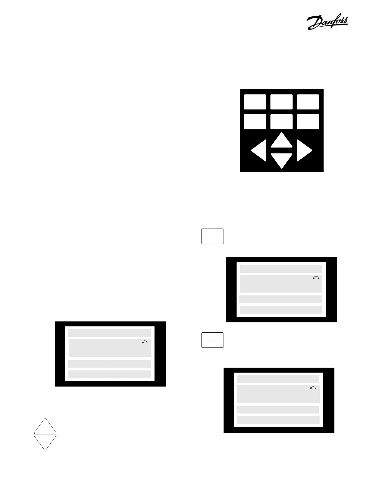
Normal Display
In normal operational mode after start up, the top line of the
display (line 1) identifies the value displayed in line 2. The large
display (line 2) shows a value, in this case the drive output in
hertz. The setup number and direction of motor rotation is
also shown. The bottom line (line 4) is the status line. This line
displays the current operational status of the drive. The
illustration below indicates that the drive is running at 40 HZ
output.
Pressing the up [+] or down [-] keys on the
keypad in this mode changes the data shown
in line 2. Thirty-one different diagnostic values
are identified (in line 1) and displayed (in line 2)
by scrolling through the display data. Setpoints,
feedback, operational hours, digital and analog
input status, relay output status, and many other
system functions are identified and their values
shown in real-time.
DISPLAY
STATUS
QUICK
MENU
CHANGE
DATA
CANCEL
MENU
OK
+
–
On the VLT 4000/6000/8000 series drives, the [DISPLAY/
STATUS] key is identified as the [DISPLAY MODE] key and
operates in the same manner described.
+
–
40.0Hz
SETUP
1
RUNNING
66% 82.1% 19.4A
Line 1
Pressing the [DISPLAY/STATUS] key on the
keypad toggles between the default setting and
the programmable three meter display in line 1.
To identify the 3 meters displayed in line 1, press
and hold the [DISPLAY/STATUS] key. The identity
of the meter is displayed while the key is
pressed.
40.0Hz
SETUP
1
RUNNING
REF% TORQ% CURR.A
The values displayed in lines 1 and 2 can be programmed
from a list of options. See programming in the operator's
manual for details.
40.0Hz
SETUP
1
RUNNING
Line 1
Line 2
Line 3
Line 4
FREQUENCY
 Loading...
