6-11
VLT is a registered Danfoss trademark
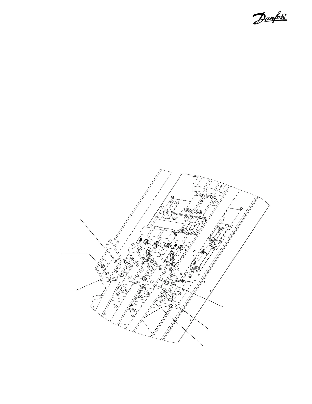
Figure 6-10. D2 SCR/Diode Module (1 of 4)
6.11 SCR/Diode Module D2 Units
1. Remove lower DC capacitor bank per instruction.
2. Remove input terminal plate per instructions.
3. Remove retaining nuts (8mm) from SCR input bus
bars.
4. Note the color coding for each of three wires
attached to retaining studs. Ensure that correct
wire is attached to applicable stud upon
reassembling. Remove wiring from studs.
5. Remove screw (T30) from terminal 1 of each
SCR/Diode module by accessing screw through
access hole in SCR/Diode input bus bar. Remove
SCR input bus bars.
6. Remove each IGBT output bus bar by removing
nut (13mm) from stud. Also remove retaining
screw (T40) at other end of IGBT output bus bars
(not shown).
CONTINUED NEXT PAGE
SCR/Diode input bus bar
BB21 or BB22 per drive
power rating
SCR/Diode input bus bar
retaining nut and stud
(Steps 3 & 4)
SCR/Diode terminal
screw (Step 5)
IGBT output bus bar BB32
(Step 6)
IGBT output bus bar
retaining nut (Step 6)
SCR/Diode terminal
screw (Step 5)
 Loading...
