4-5
VLT is a registered Danfoss trademark
Signal and Power Wiring Considerations for
Drive Electromagnetic Compatibility
Following is an overview of general signal and power wiring
considerations when addressing the Electromagnetic
Compatibility (EMC) concerns for typical commercial and
industrial equipment. Only certain high-frequency
phenomena (RF emissions, RF immunity) are discussed.
Low-frequency phenomena (harmonics, line voltage
imbalance, notching) are not covered. Special installations
or compliance to the European CE EMC directives will
require strict adherence to relevant standards and is not
presented here.
Effects of EMI
While Electromagnetic Interference (EMI) related
disturbances to drive operation are uncommon, the
following detrimental EMI effects may be seen:
Motor speed fluctuations
Serial communication transmission errors
Drive CPU exception faults
Unexplained drive trips
A disturbance to other nearby equipment is more common.
Generally, other industrial control equipment has a high level
of EMI immunity. However, non-industrial, commercial, and
consumer equipment is often susceptible to lower levels of
EMI. Detrimental effects to these systems may include the
following:
Pressure/flow/temperature signal transmitter
signal distortion or aberrant behavior
Radio and TV interference
Telephone interference
Computer network data loss
Digital control system faults
Sources of EMI
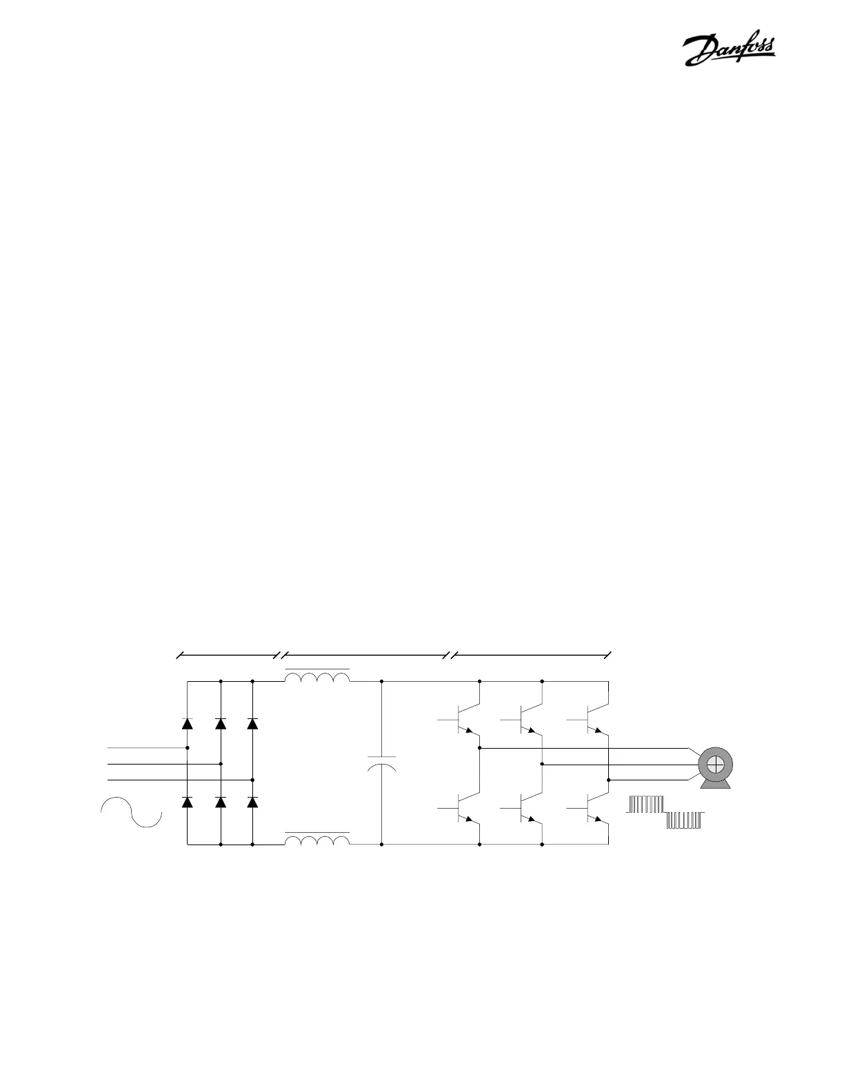
Modern adjustable frequency drives (see Figure 4-1) utilize
Insulated-Gate Bipolar Transistors (IGBTs) to provide an
efficient and cost effective means to create the Pulse Width
Modulated (PWM) output waveform necessary for accurate
motor control. These devices rapidly switch the fixed DC
bus voltage creating a variable frequency, variable voltage
PWM waveform. This high rate of voltage change [dV/dt] is
the primary source of the drive generated EMI.
AC Line
Rectifier DC Bus Inverter
Motor
Filter reactor
IGBT
Filter capacitor
PWM waveformSine wave
Figure 4-1. Adjustable Frequency Drive Functionality Diagram
The high rate of voltage change caused by the IGBT switching creates
high frequency EMI.
 Loading...
