6-14
VLT is a registered Danfoss trademark
Note
Note which gate leads are attached to each
module to ensure that leads are reconnected to
correct modules upon reassembly.
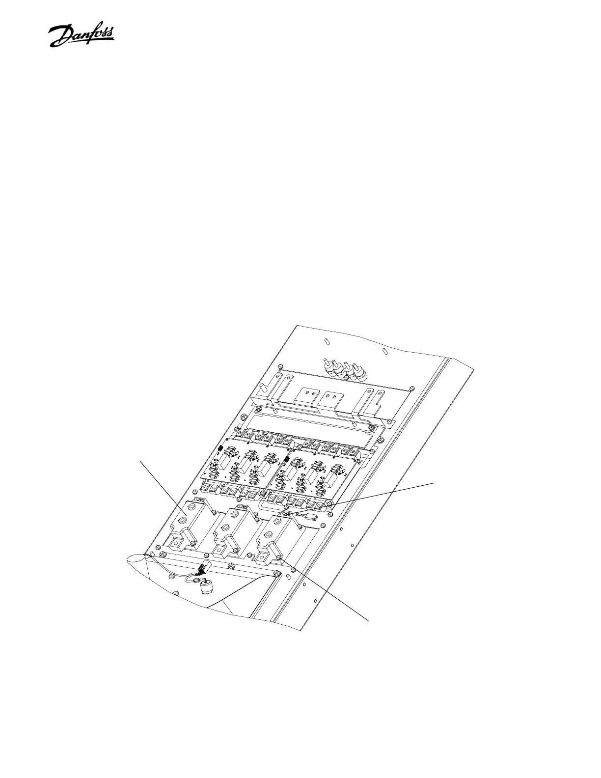
11. Remove SCR gate lead connectors from
modules.
12. Remove two SCR/Diode module retaining screws
on each module (T30) and remove SCR/Diode
modules.
SCR/Diode module (Step 12)
SCR/Diode module mounting screws
(Step 12)
SCR gate lead connectors
(Step 11)
REASSEMBLY
1. To replace SCR/Diode modules, follow instructions
included with replacement module.
2. Reassemble in reverse order. Tighten remaining
T25 and 8mm screws to 20 in-lbs (2.25 Nm) and
T30 to 35 in-lbs (4 Nm).
3. Be sure to cross tighten replacement unit per
instructions with spare part.
Figure 6-10. D2 SCR/Diode Module (4 of 4)
 Loading...
