6-22
VLT is a registered Danfoss trademark
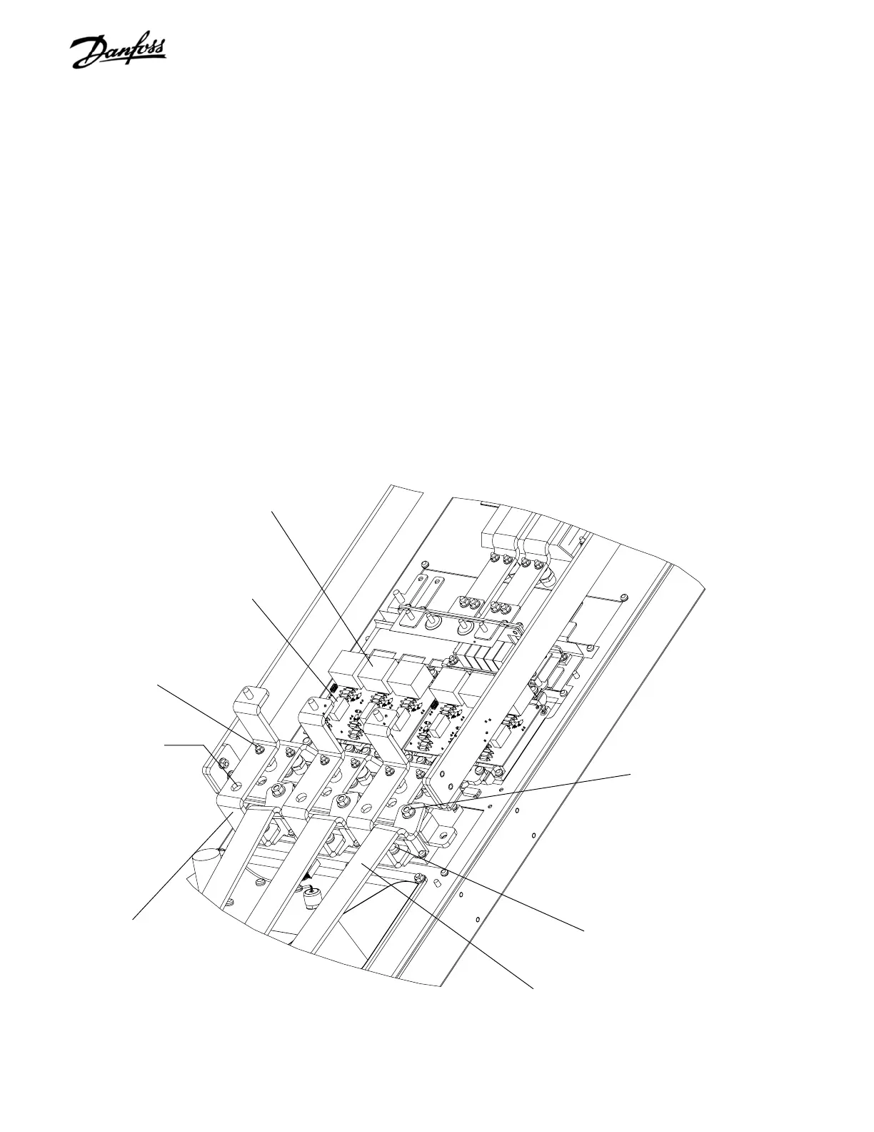
6.16 IGBT Modules D2 Units
1. Remove capacitor banks per instructions.
2. Note IGBT gate signal cables connected between
gate drive card connectors MK102 (U), MK103
(V), and MK104 (W) and IGBTs. These will need to
be reconnected in same locations during
reassembly. Units with brake option will have
brake cabling from MK105 in addition. Disconnect
cables at connectors on IGBT modules.
3. Remove retaining nuts (8mm) from SCR input bus
bars.
IGBT gate signal
input terminal
(Step 2)
Snubber capacitor
Figure 6-15. D2 IGBT Modules (1 of 3)
4. Note the color coding for each of three wires
attached to retaining studs. Ensure that correct
wire is attached to applicable stud upon
reassembling. Remove wiring from studs.
5. Remove screw (T25) from terminal 1 of each
SCR/Diode module by accessing screw through
access hole in SCR/Diode input bus bar. Remove
SCR input bus bars.
6. Remove each IGBT output bus bar by removing
nut (10mm) from stud. Also remove retaining
screw (T30) at other end of IGBT output bus bars
(not shown).
CONTINUED ON NEXT PAGE
SCR/Diode input bus bar
BB21 or BB22 per drive
power rating
SCR/Diode input bus bar
retaining nut and stud
(Steps 3 & 4)
SCR/Diode terminal
screw (Step 5)
IGBT output bus bar BB32
(Step 6)
IGBT output bus bar
retaining nut (Step 6)
SCR/Diode terminal
screw (Step 5)
 Loading...
