5-27
VLT is a registered Danfoss trademark
5.2.14 Input Terminal Signal Tests
The presence of signals on either the digital or analog input
terminals of the drive can be verified on the drive display. Digital
or analog input status can be selected in the display using the
[DISPLAY MODE] key and the [+] and [-] keys on the keypad.
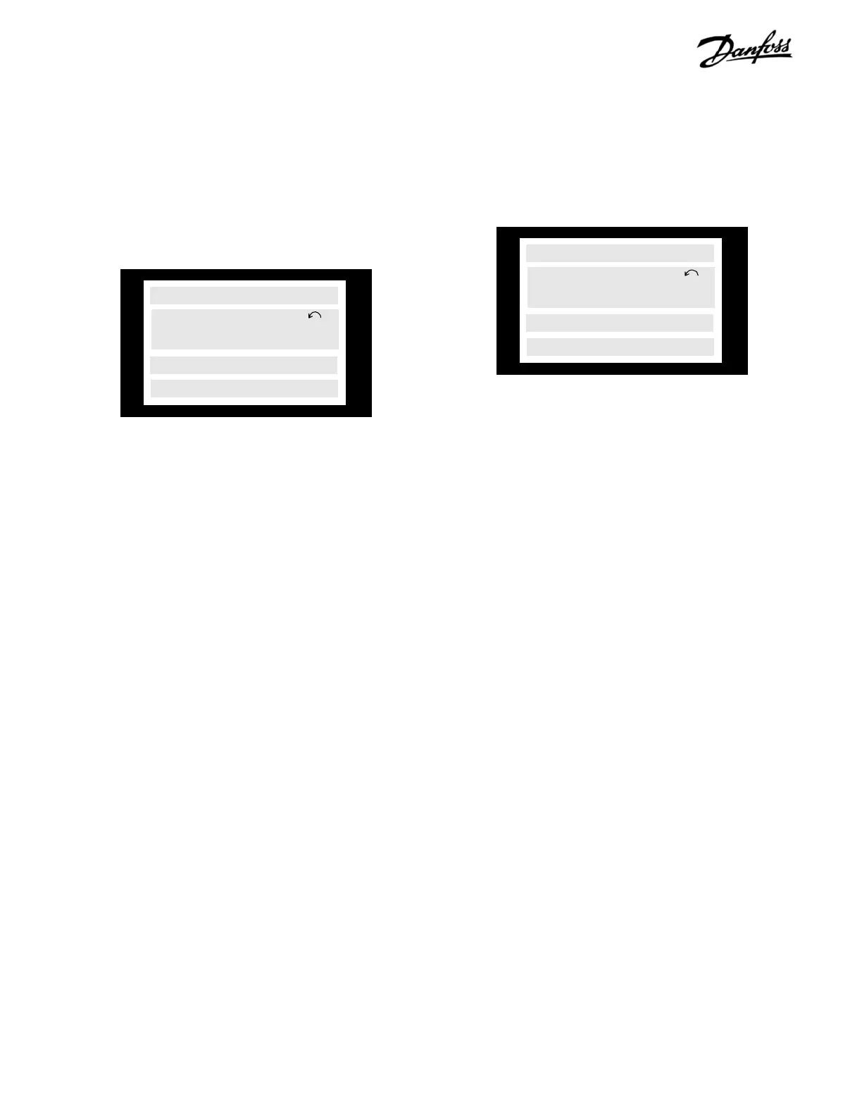
5.2.14.1 Digital inputs
With digital inputs displayed, control terminals 16-33 are shown
left to right, with a 1 indicating the presence of a signal.
If the desired signal is not present in the display, the problem
may be either in the external control wiring to the drive or a
faulty control card. To determine the fault location, use a volt
meter to test for voltage at the control terminals
.
Verify the control voltage power supply is correct as follows.
1. With a voltmeter measure voltage at control
card terminal 12 and 13 with respect to terminal
20. Meter should read between 21 and 27 VDC.
If the 24 V supply voltage is not present, conduct the Control
Card Test (5.2.15) earlier in this section.
If the 24 V is present proceed with checking the individual
inputs as follows.
2. Connect (-) negative meter lead to reference
terminal 20.
3. Connect (+) positive meter lead to terminals 16,
17, 18, 19, 27, 29, 32, and 33 in turn.
Presence of a signal at the desired terminal should correspond
to the digital input display reading. A reading of 24 VDC indicates
the presence of a signal. A reading of 0 VDC indicates no
signal is present.
5.2.14.2 Analog inputs
The value of signals on analog input terminals 53, 54, and 60
can also be displayed.
The voltage on terminals 53 and 54, or the current in milliamps
for terminal 60 is shown in line 2 of the display.
If the desired signal is not present in the display, the problem
may be either in the external control wiring to the drive or a
faulty control card. To determine the fault location, use a volt
meter to test for a signal at the control terminals.
Verify the reference voltage power supply is correct as follows.
1. With a voltmeter measure voltage at control
card terminal 50 with respect to terminal 55.
Meter should read between 9.2 and 11.2 VDC.
If the 10 V supply voltage is not present, conduct the Control
Card Voltage Test earlier in this section.
If the 10 volts is present proceed with checking the individual
inputs as follows.
2. Connect (-) negative meter lead to reference
terminal 55.
3. Connect (+) positive meter lead to desired
terminal 53, 54 or 60.
For analog input terminals 53 and 54, a DC voltage between 0
and +10 VDC should be read to match the analog signal being
sent to the drive.
For analog input terminal 60, a reading of 0.9 to 4.8 VDC
corresponds to a 4 to 20ma signal.
Note that a (-) minus sign preceding any reading above indicates
a reversed polarity. In this case, reverse the wiring to the analog
terminals.
00101000
SETUP
1
DIGITAL INPUT
REMOTE RUNNING
MA
SETUP
1
ANALOG INPUT 60
REMOTE RUNNING
12
 Loading...
