7-13
VLT is a registered Danfoss trademark
7.14 IGBT Modules
1. Remove both DC capacitor banks in accordance
with procedure.
2. Remove Input Terminal Plate in accordance with
procedure.
3. Remove wire retaining nut (10 mm) from each of
3 SCR input bus bars.
4. Note color coding for each of 3 wires attached to
retaining studs. Ensure that correct wire is
attached to applicable stud upon reassembly.
Remove wiring from studs.
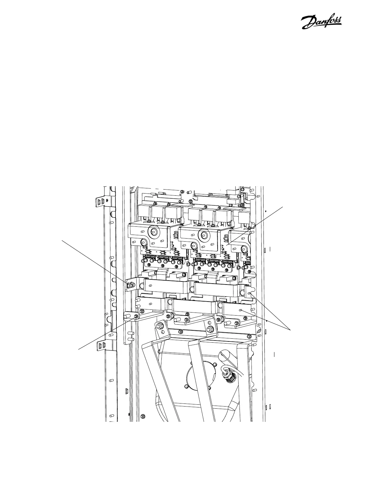
Figure 7-12. IGBT Modules (1 of 4)
5. Remove wire retaining nut (8 mm) from SCR
output bus bars. One from (+) DC bus bar and
one from (–) DC bus bar.
6. Note color coding for each wire attached to
retaining studs. Ensure that correct wire is
attached to applicable stud upon reassembly.
Remove wiring from studs.
7. Remove 4 retaining nuts (13 mm) on side of bus
bars, 2 on each bus bar.
CONTINUED NEXT PAGE
Wire retaining nut on
bus bar BB41 (Step 3)
Wire retaining nuts for
output bus bars BB42
(Steps 5 & 6)
Retaining nuts
(Step 7)
IGBT board
 Loading...
