7-9
VLT is a registered Danfoss trademark
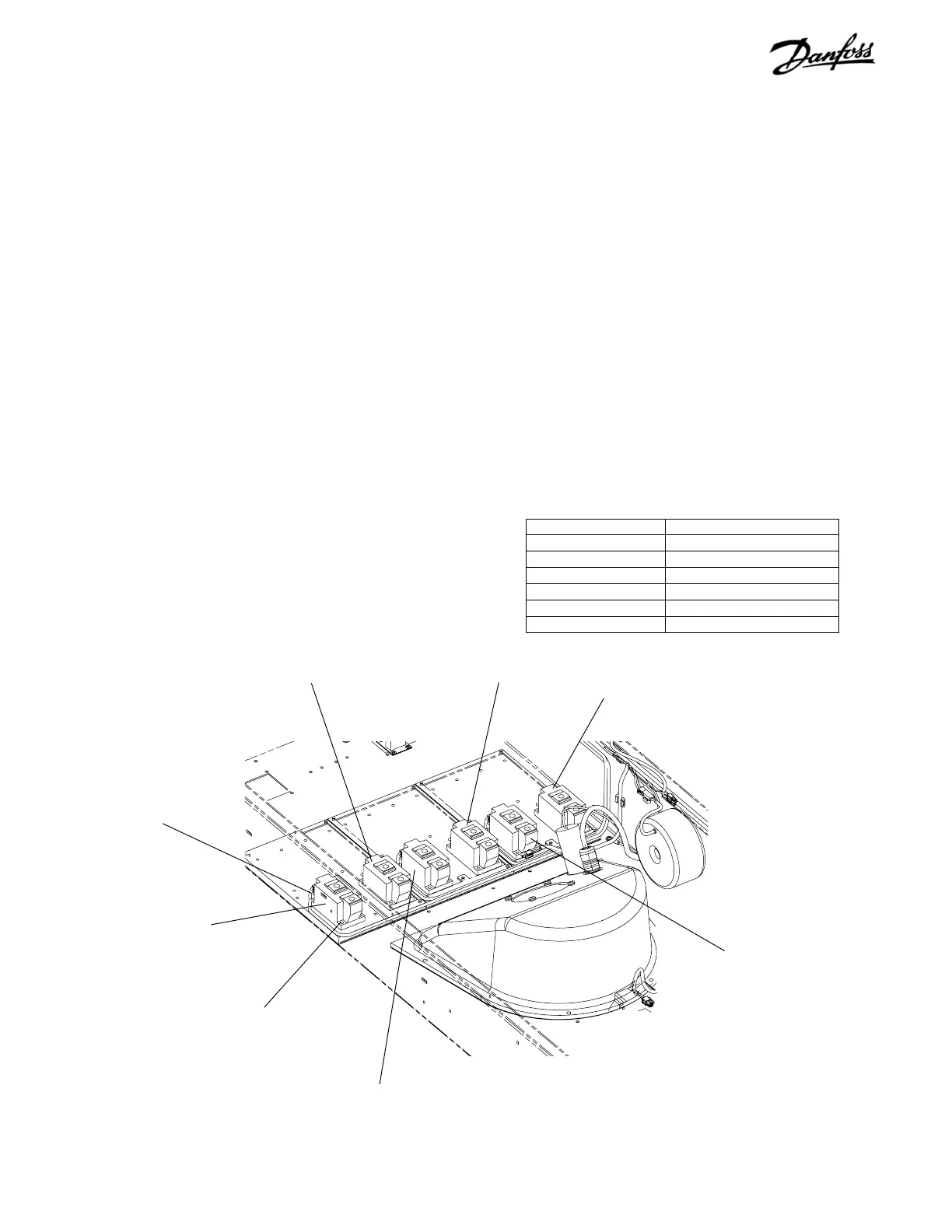
11. Note which gate lead connects to each SCR
module. Ensure that correct wire is attached to
applicable SCR upon reassembly. Remove wiring
from each SCR modules. Connector is keyed for
proper reinstallation. DO NOT force connection.
12. Remove SCR or diode module by removing 4
retaining screws (T25) from each module.
REASSEMBLY
CAUTION
Equipment Damage!
Do not reverse SCR and diode modules during
installation. Reversing SCR and diode modules
can result in equipment damage.
Note
For each AC input phase there is one SCR
module and one diode module. The SCR is on
the left, diode on the right (as seen facing upright
unit). There are three pair. Only the SCR module
has a connection pin for the gate signals.
1. Replace SCR and diode modules in accordance
with instructions included with replacement
modules.
2. Reassemble in reverse order.
SCR module SCR1
Diode module D1
SCR gate lead connection
(Step 11)
Figure 7-8. SCR and Diode Modules (3 of 3)
Diode module D2
Diode module D3
SCR module SCR2
SCR module SCR3
Retaining screw
(Step 12)
Attaching Hardware Tightening Torque
T50 Per spare part instruction
T25 Per spare part instruction
17 mm 170 in-lbs ( 19.2 Nm)
13 mm 85 in-lbs (9.6 Nm)
10 mm 35 in-lbs (4.0Nm)
8 mm 20 in-lbs (2.25 Nm)
 Loading...
