5-22
VLT is a registered Danfoss trademark
An incorrect reading of a gate signal indicates the gate drive
card is defective or the signal has been lost prior to it arriving
at the gate card. The gate signals can then be checked with
the signal test board to verify their presence from the control
card to the power card as follows.
12. Insert signal test board into interface card
connector MK104.
13. With scope probe ground connected to
terminal 4 (common) of signal board, measure
six gate signals at signal board terminals 25
through 30.
CONTINUED ON NEXT PAGE
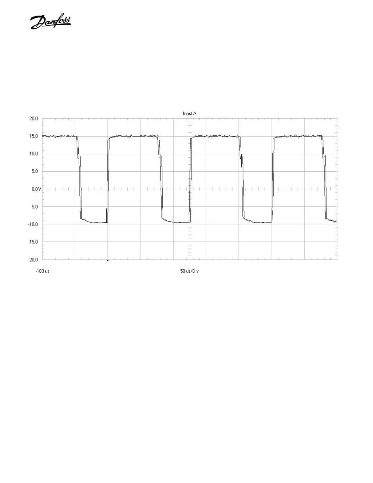
Figure 5-14. Gate Signal Waveform from Gate Drive Card
11. If using a DVM, measure pins 1 and 2 of each
connector. Waveform to IGBTs is a square
wave that goes positive to 14 VDC and
negative to -9 VDC. Average voltage read by
DVM should be 2.2 to 2.5 VDC.
When using an oscilloscope, the readings should appear as in
Figure 5-14.
IGBT Gate Signal measured on the Gate Drive Card: 5 volts per division vertical scale, 50
microseconds per division time scale. Unit running at 30 Hz.
 Loading...
