EasyManuals Logo
Home>Danfoss>DC Drives>VLT AutomationDrive FC 361

Danfoss VLT AutomationDrive FC 361 Programming Guide

Danfoss VLT AutomationDrive FC 361
196 pages
To Next Page IconTo Next Page
To Previous Page IconTo Previous Page
Page #130 background imageLoading...
Page #130 background image
14-01 Switching Frequency
Select the frequency converter switching frequency. Changing
the switching frequency reduces acoustic noise from the motor.
Default values depend on power size.
Option: Function:
[8] 6.0 kHz
[9] 7.0 kHz
[10] 8.0 kHz
[11] 10.0 kHz
[12] 12.0kHz
[13] 14.0 kHz
[14] 16.0kHz
14-03 Overmodulation
Option: Function:
[0] O Select [0] O to avoid torque ripple
on the motor shaft.
[1] On Select [1] On to obtain extra DC-link
voltage and torque on the motor
shaft.
14-04 Acoustic Noise Reduction
Option: Function:
[0] * O No change of the acoustic motor
switching noise.
[1] On Select to reduce the acoustic noise
from the motor.
14-06 Dead Time Compensation
Option: Function:
[0] O No compensation.
[1] * On Activates dead-time compensation.
4.13.1 14-1* Mains On/O
Parameters for conguring mains failure monitoring and
handling. If a mains failure appears, the frequency
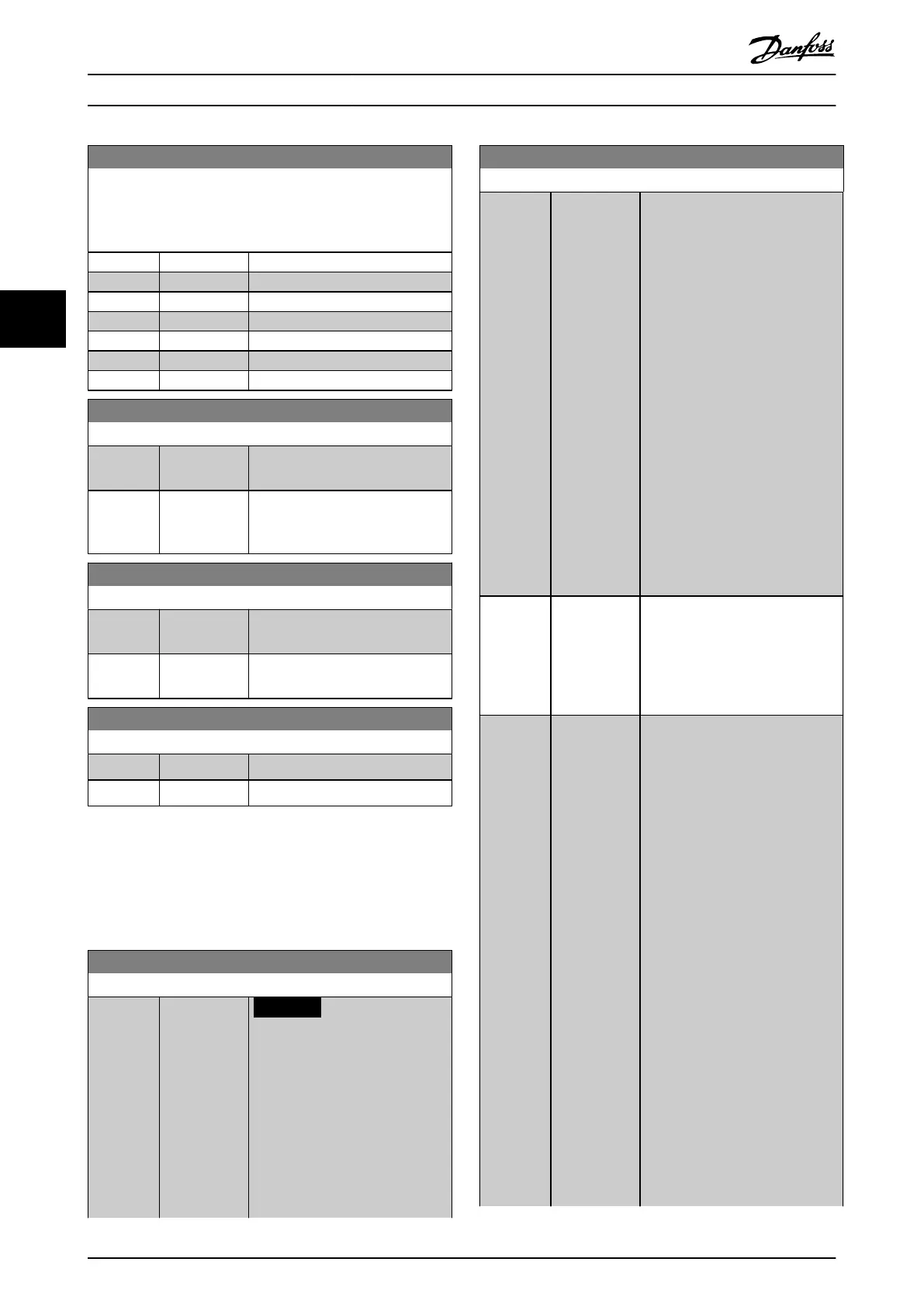
converter tries to continue in a controlled way until the
power in the DC link is exhausted.
14-10 Mains Failure
Option: Function:
NOTICE
Parameter 14-10 Mains Failure
cannot be changed while the
motor is running.
Parameter 14-10 Mains Failure is
typically used where very short
mains interruptions (voltage dips)
are present. At 100% load and a
short voltage interruption, the DC
voltage on the main capacitors
14-10 Mains Failure
Option: Function:
drops quickly. For larger frequency
converters, it only takes a few
milliseconds before the DC level
drops to about 373 V DC, and the
IGBTs cut o and lose the control of
the motor. When mains is restored,
and the IGBTs start again, the
output frequency and voltage
vector do not correspond to the
speed/frequency of the motor, and
the result is normally an
overvoltage or overcurrent, mostly
resulting in a trip lock.
Parameter 14-10 Mains Failure can
be programmed to avoid this
situation.
Select the function according to
which the frequency converter
must act when the threshold in
parameter 14-11 Mains Fault Voltage
Level is reached.
[0] * No function The frequency converter does not
compensate for a mains
interruption. The voltage on the
DC-link drops quickly and motor
control is lost within milliseconds to
seconds. Trip lock is the result.
[1] Ctrl. ramp-
down
Control of the motor remains with
the frequency converter, and the
frequency converter performs a
controlled ramp down from
parameter 14-11 Mains Fault Voltage
Level. If parameter 2-10 Brake
Function is [0] O or [2] AC brake,
the ramp follows the overvoltage
ramping. If parameter 2-10 Brake
Function is [1] Resistor Brake, the
ramp follows the setting in
parameter 3-81 Quick Stop Ramp
Time. This selection is useful in
pump applications, where the
inertia is low and the friction is
high. When mains is restored, the
output frequency ramps the motor
up to the reference speed (if the
mains interruption is prolonged, the
controlled ramp down may bring
the output frequency down to 0
RPM, and when the mains is
restored, the application is ramped
up from 0 RPM to the previous
reference speed via the normal
ramp up). If the energy in the DC-
Parameter Descriptions VLT® AutomationDrive FC 361
128 Danfoss A/S © 03/2019 All rights reserved. MG06J202
44

Table of Contents

Other manuals for Danfoss VLT AutomationDrive FC 361

Questions and Answers:

Question and Answer IconNeed help?

Do you have a question about the Danfoss VLT AutomationDrive FC 361 and is the answer not in the manual?

Danfoss VLT AutomationDrive FC 361 Specifications

General IconGeneral
BrandDanfoss
ModelVLT AutomationDrive FC 361
CategoryDC Drives
LanguageEnglish

Related product manuals