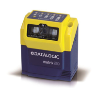
MATRIX 210™ PARAMETERS LIST
35
4
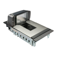
4.6 READING SYSTEM LAYOUT
25 PIN CONNECTOR MODELS
ETHERNET MODELS
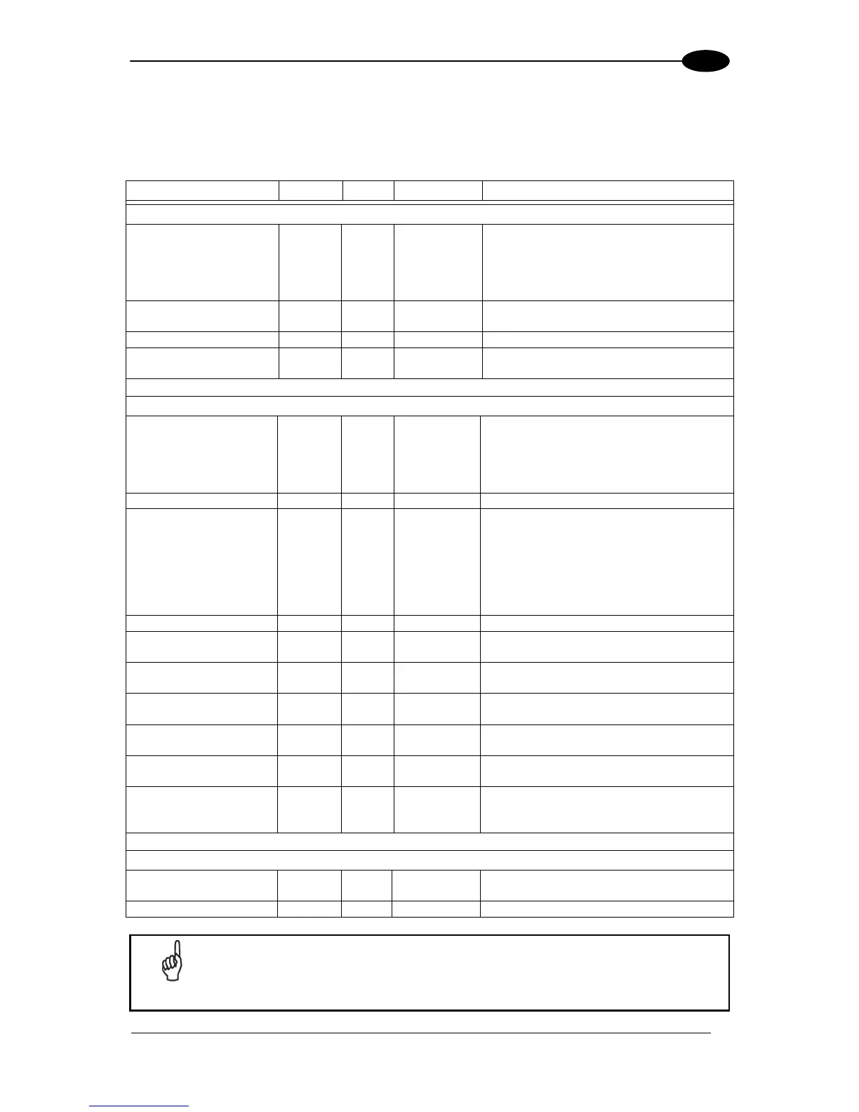
PARAMETER TYPE SEL STRING DATA
READING SYSTEM LAYOUT
Device Network Setting
1 1 ESC A R 0 = Alone Or ID-NET
1 = Master RS232 (Type A)
2 = Slave RS232 (Type A)
3 = Master RS232 (Type M)
4 = Slave RS232 (Type M)
Number of Slaves (Type
A or M)
0 ESC A S Range: 1 to 9
Link Failure String 2 ESC A T Length: 0 to 32
Link Failure Timeout
(ms)
0 ESC A U Range: 10 to 10000
DEVICE NETWORK SETTING
Topology Role 1 1 ESC A a 0 = Other
1 = Master (Synchronized)
2 = Slave (Synchronized)
3 = Master (Multidata)
4 = Slave (Multidata)
Slave Address 0 ESC A b Range: 1 to 31
Network Baud Rate
(bps)
1 1 ESC A c 0 = 19200
1 = 38400
2 = 57600
3 = 125 Kb
4 = 250 Kb
5 = 500 Kb
6 = 1 Mb
Link Failure String 2 ESC A d Length: 0 to 32
Link Failure Timeout
(ms)
0 ESC A e Range: 10 to 10000
Header String
(Slave Multidata)
2 ESC A f Length: 0 to 128
Terminator String
(Slave Multidata)
2 ESC A g Length: 0 to 128
Address TX
(Master Multidata)
1 1 ESC A h 0 = Disabled
1 = Enabled
Address Header String
(Master Multidata)
2 ESC A i Length: 0 to 32
Address Separator
String
(Master Multidata)
2 ESC A l Length: 0 to 32
EXPECTED SLAVE DEVICE (DEPTH: n = 1 to 31)
Device Status #n 1 1 ESC J #n 0 = Disabled
1 = Enabled
Device Description #n 2 ESC K #n Length: 0 to 16
NOTE
Special characters <FE
H
> and <FD
H
> must be added after #n in the
programming string to indicate parameter Depth > 9. Refer to paragraph 3.2
for further details.
 Loading...