3.2.5 Output settings
The output defines the reaction from the system, when the function is activated. A delay
time can be set for a function (no delay, if set to 0 s).
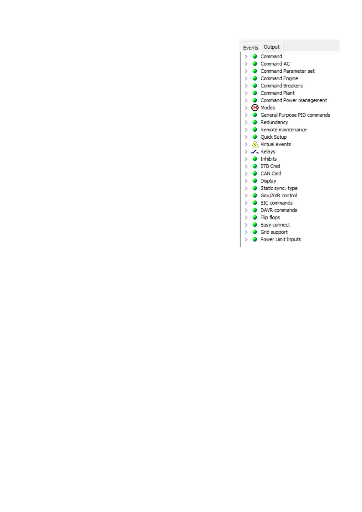
The groups in the Output window depend on the controller type and its options. Each
group contains a number of outputs. See the List of outputs chapter for details.
NOTE
If a relay output is chosen, this relay must be configured as a limit relay
output in I/O setup or in the parameter list.
3.3 Definitions
TRUE state
A TRUE state of an input/event will be detected, if the condition defined in the input event is met. For example:
• Digital input is TRUE when activated (12/24V DC applied).
• Alarm condition is TRUE when the alarm is present.
• Mode condition is TRUE when the mode is selected.
FALSE state
A FALSE state of an input event will be detected, if the condition defined in the input event is not met. For example:
• Digital input is FALSE when deactivated (12/24V DC not applied).
• Alarm condition is FALSE when the alarm is not present.
• Mode condition is FALSE when the mode is not selected.
3.4 Examples
By using the events, rules can be made for the use of the M-Logic.
3.4.1 Virtual events
Virtual events are used to expand the number of events in a logic sequence. For example, the output of Logic 1 can be used to
continue the sequence in Logic 2.
Application note 4189341276B EN Page 11 of 50
 Loading...


