EasyManuals Logo

Dell PowerEdge 1950 Installation Guide

Dell PowerEdge 1950
202 pages
To Next Page IconTo Next Page
To Previous Page IconTo Previous Page
Page #16 background imageLoading...
Page #16 background image
14 Four-Post Rack Installation
Installing Chassis Static Rail Modules (Static Rail Kits Only)
NOTE: You do not need to remove the optional front bezel to install or remove the chassis static rail modules from
the chassis.
1
To install a rail module, locate the three keyhole slots on the rail module and the corresponding
shoulder screws on the side of the system (see Figure 1-6).
2
Place the rail module against the side of the system so that the shoulder screws fit through the round
portion of the keyhole slots, then slide the module towards the back of the system.
3
Repeat steps 1 and 2 to install the other rail module.
To remove a
rail module
from the chassis, pull up on the release latch, then slide the rail forward and
remove the rail module from the chassis.
Figure 1-6. Installing and Removing Static Rail Chassis Modules
1 keyhole slots (6) 2 shoulder screws (6) 3 release latch
4 rail modules (2) 5 system
4
2
3
1
5

Table of Contents

Other manuals for Dell PowerEdge 1950

Questions and Answers:

Question and Answer IconNeed help?

Do you have a question about the Dell PowerEdge 1950 and is the answer not in the manual?

Dell PowerEdge 1950 Specifications

General IconGeneral
Processor Sockets2
ChipsetIntel 5000X
Memory Slots8 DIMM slots
NetworkDual embedded Broadcom NetXtreme II 5708 Gigabit Ethernet
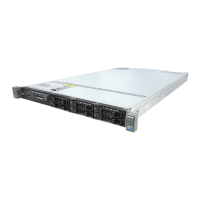
Form Factor1U Rack
ProcessorIntel Xeon 5100, 5300 series
MemoryUp to 32GB DDR2
StorageSAS or SATA
Drive BaysTwo 3.5" SAS or SATA drives or Four 2.5" SAS or SATA drives
RAID ControllerPERC 5/i, PERC 6/i
Power Supply670W redundant power supply (optional)
Operating System SupportMicrosoft Windows Server, Red Hat Linux, SUSE Linux

Related product manuals