Installing Enclosure Components 275
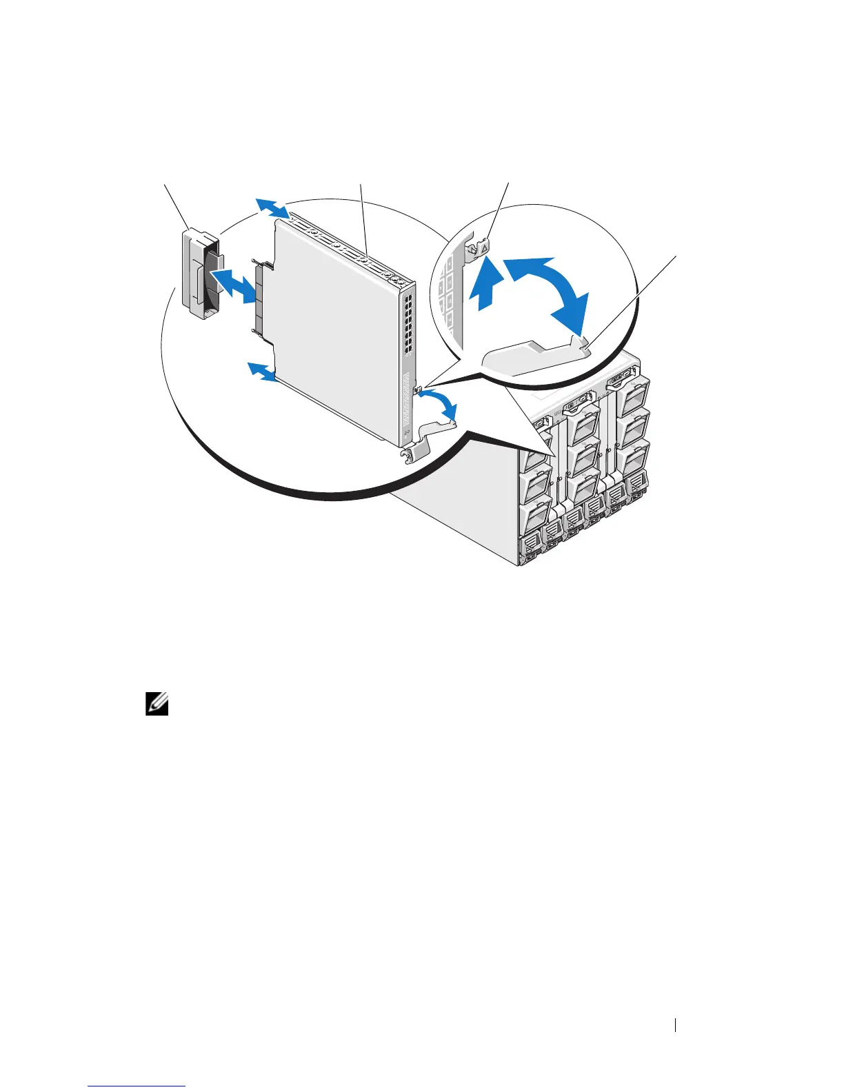
Figure 4-6. Removing and Installing an I/O Module
Installing an I/O Module
NOTE: The I/O module must be installed in the appropriate I/O bay. See "Guidelines
for Installing I/O Modules" on page 48.
When installing I/O modules or blanks in the I/O module bays in the back of
our system enclosure, you must install them in right-to-left order:
• A module (or blank) must be installed in bay A2, then bay B2, then bay
C2.
• Next, a module (or blank) must be installed in bay C1, then bay B1, then
bay A1.
1 I/O connector cover 2 I/O module
3 release latch 4 handle
 Loading...