EasyManua.ls Logo

Delta ECMA-E 1315 Series User Manual

Delta ECMA-E 1315 Series
721 pages
To Next Page IconTo Next Page
To Previous Page IconTo Previous Page
Page #195 background image
Chapter 6 Control Mode of Operation ASDA-A2
6-40 Revision February, 2017
Unit
dB
Range
0 ~ 32
Data Size
16-bit
Format
Decimal
Settings
The third group of resonance suppression (Notch filter) attenuation
rate. Set the value to 0 to disable the function of Notch filter.
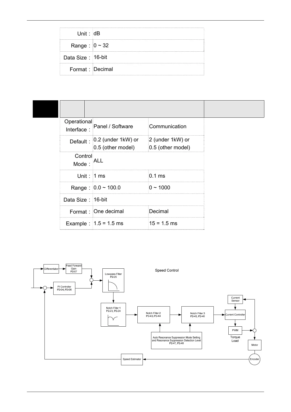
P2-25 NLP Low-pass Filter of Resonance Suppression
Address: 0232H
0233H
Operational
Interface
Panel / Software Communication
Related Section:
6.3.7
Default
0.2 (under 1kW) or
0.5 (other model)
2 (under 1kW) or
0.5 (other model)
Control
Mode
ALL
Unit
1 ms 0.1 ms
Range
0.0 ~ 100.0 0 ~ 1000
Data Size
16-bit
Format
One decimal Decimal
Example
1.5 = 1.5 ms 15 = 1.5 ms
Settings
Set the low-pass filter of resonance suppression. When the value is set
to 0, the function of low-pass filter is disabled.

Table of Contents

Questions and Answers:

Delta ECMA-E 1315 Series Specifications

General IconGeneral
BrandDelta
ModelECMA-E 1315 Series
CategoryServo Drives
LanguageEnglish

Summary

Chapter 1 Inspection and Model Explanation

1.1 Inspection

Instructions for inspecting the servo drive and motor to prevent damage during purchasing and delivery.

1.2 Product Model

Details on identifying and understanding the model names of ASDA-A2 series servo drives and ECMA series servo motors.

Chapter 2 Installation

Chapter 3 Wiring

Chapter 4 Panel Display and Operation

Chapter 5 Trial Operation and Tuning

5.1 Inspection without Load

Details the procedures for inspecting the servo motor and drive before operation, without applying power.

5.2 Applying Power to the Servo Drive

Provides instructions on correctly wiring and applying power to the servo drive, including voltage and wiring checks.

5.3 JOG Trial Run without Load

Explains how to perform a JOG trial run without load for testing motor and drive functionality.

5.6 Tuning Procedure

Covers the process of tuning the servo drive, including inertia estimation and various tuning methods.

Chapter 6 Control Mode of Operation

6.1 Selection of Operation Mode

Describes the available operation modes: Position, Speed, Torque, Dual, and Multi-modes.

Chapter 7 Motion Control

7.10 Parameter Settings

Details various parameters related to motion control, including target speed, acceleration/deceleration, and PR definitions.

Chapter 8 Parameters

8.1 Parameter Definition

Defines parameters, their grouping, communication addresses, and control modes.

8.2 List of Parameters

Provides a comprehensive list of parameters, including abbreviations, functions, defaults, and related sections.

8.3 Parameter Description

Details the function, default values, units, and related sections for various parameters.

Chapter 9 Communications

9.1 RS-485 & RS-232 Communication Hardware Interface

Explains the hardware interface for RS-485 and RS-232 communication, including configuration and wiring.

9.2 RS-485 / RS-232 Communication Parameters Setting

Details the essential parameters for servo drive communication, such as address, transmission speed, and protocol.

Chapter 10 Troubleshooting

10.1 Alarm of Servo Drive

Lists common servo drive alarms, their descriptions, corresponding DO signals, and servo status.

10.2 Alarm of CANopen Communication

Details CANopen communication alarms, their descriptions, corrective actions, and corresponding DO/Servo status.

10.3 Alarm of Motion Control

Lists alarms related to motion control, including causes, checking methods, and corrective actions.

10.4 Causes and Corrective Actions

Provides a table of common causes and corrective actions for servo drive alarms like Over current, Over voltage, etc.

10.5 Corrective Actions after the Alarm Occurs

Lists corrective actions for various alarms, suggesting steps like turning DI.ARST on or re-powering the servo drive.

Chapter 11 Specifications

11.1 Specifications of Servo Drives

Presents detailed specifications for ASDA-A2 series servo drives, including 220V and 400V series.

Chapter 12 Absolute System

12.1 Backup Battery Boxes

Covers safety precautions, specifications, dimensions, and connection cables for backup battery boxes.

12.3 System Initialization Procedure and Operation

Explains the system initialization process, including procedures for absolute system setup via digital I/O or parameters.

12.7 Alarms for Absolute System

Lists common alarms for absolute systems, including causes and corrective actions for encoder voltage, gray code, etc.

Appendix B Maintenance and Inspection

Inspection before operation

Checks to perform before applying power, including wiring, electrical conductivity, and control switch status.

Related product manuals