EasyManua.ls Logo

Delta TP70P User Manual

Delta TP70P
65 pages
To Next Page IconTo Next Page
To Previous Page IconTo Previous Page
Page #12 background image
Chapter 1 Introduction
1-9
Model
Item
TP70P
-16TP1R
TP70P
-32TP1R
TP70P
-22XA1R
TP70P
-21EX1R
TP70P
-RM0
Storage
temperature
-20°C~60°C
Vibration/Sho
ck resistance
International standards IEC61131-2, IEC 68-2-6 (TEST Fc)/IEC61131-2 & IEC 68-2-27 (TEST
Ea)
Dimensions 175.8 × 108.6 × 59.2 mm (Width × Height × Depth)
Cooling Transfer of thermal energy via convection
1.6.2
Electrical Specifications for Digital Input Terminals
Electrical specifications for digital input terminals
Model
Item
24 V DC (-15% ~ 20%) single common terminal
Input terminal X0, X1 X2~X7, X10~X17
Input form
Sinking current: Current flows into the terminal S/S.
Sourcing current: Current flows from the terminal S/S.
Input voltage (±10%) 24 V DC, 5 mA
Input impedance 4.7 kilohm
Maximum input
frequency
10 kHz 60 Hz
OffOn > 16.5 V DC
Action levle
OnOff < 8 V DC
OffOn <20 us Response
time
OnOff <50 us
10 ms
1.6.3
Electrical Specifications for Digital Output Terminals
Model
Item
Electrical specifications for digital output terminals
Output type Relay
Voltage 250 V AC, < 30 V DC
Resistance 1.5 A/point (5 A/COM)
Inductance #1
Current
Bulb 20 W DC/100 W AC
OffOn Response
time
OnOff
Approximately 10 ms
Maximum output
frequency
50 Hz
#1: Life curves
Contact
Current(A)
20
0.5
0.1
0.2
30
50
0.3 0.7
12
200
300
500
100
1,000
2,000
3,000
O
p
e
r
a
t
i
o
n
(
X
1
0
)
3
120VAC Resistive
30VDC Inductive(t=7ms)
240VAC Inductive(cos 0.4)
ψ
=
120VAC Inductive(cos =0.4)
ψ
30VDC
Inductive
(t=40ms)

Table of Contents

Question and Answer IconNeed help?

Do you have a question about the Delta TP70P and is the answer not in the manual?

Delta TP70P Specifications

General IconGeneral
BrandDelta
ModelTP70P
CategoryMonitor
LanguageEnglish

Summary

Chapter 1 Introduction

1.1 Introduction of TP70P

Overview of TP70P capabilities, functions, and connectivity options.

1.2 Related Manuals

Lists and briefly describes other essential manuals for the TP70P system.

1.3 Profile and Dimensions

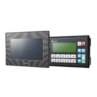
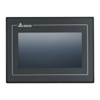
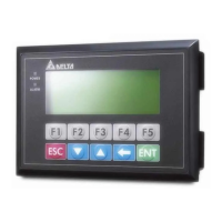
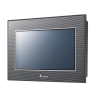
Details the physical appearance, views, and exact measurements of the TP70P.

1.4 Definitions of External Connectors

Explains the pin assignments and functions of all external connection ports.

1.5 Functional Specifications

Outlines the performance characteristics, display, and I/O capabilities.

1.6 Electrical Specifications

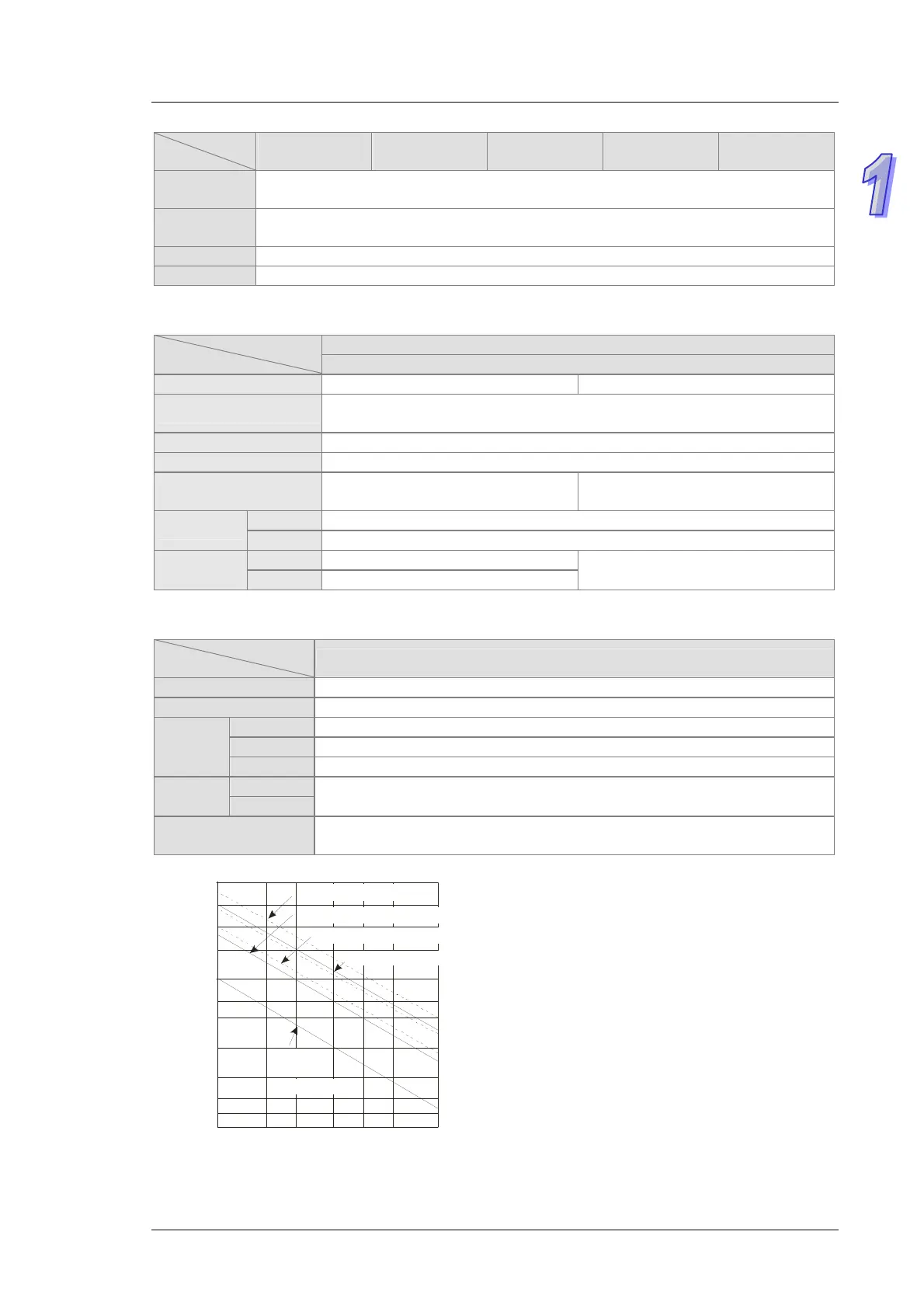
Provides detailed electrical ratings, power consumption, and immunity data.

1.7 Installation

Covers proper mounting, panel requirements, and environmental considerations.

1.8 Wiring

Guides on connecting power, input/output terminals, and communication interfaces.

1.9 Definitions of the Pins in Communication Ports

Specifies the pinout for RS-485 and RS-232 communication ports.

1.10 Controllers Supporting TP70P

Lists compatible Delta controllers and communication wiring examples.

Chapter 2 Writing Programs

2.1 Preparations

Lists required hardware, software versions, and essential tools for programming.

2.2 Wiring

Details wiring diagrams for connecting TP70P to devices like VFDs and external terminals.

2.3 Example

Demonstrates a system setup and control program for a Delta VFD with TP70P.

2.4 Writing a Program for a Text Panel

Guides on using TPEditor to create HMI programs, objects, and pages.

2.5 Writing a Program for a PLC

Explains PLC programming using WPLSoft, including project setup and logic.

2.6 Monitoring and Debugging a Program

Covers compiling, downloading, monitoring, and troubleshooting PLC programs.

Chapter 3 Frequently Asked Questions and Answers

3.1 Installing a USB Driver

Step-by-step guide for installing the USB driver to enable computer communication.

3.2 Descriptions of the Communication Ports on TP70P

Compares COM1, COM2, COM3 interfaces, modes, and settings.

3.3 Setting COM2

Details how to configure COM2 for PLC communication using specific registers and parameters.

3.4 Using COM2 as a Master Station

Explains using COM2 for master station communication with Modbus instructions.

3.5 Setting COM3

Describes setting up COM3 for text panel communication with various master/slave drivers.

3.6 Setting an RTU Mode for COM3

Guides on configuring COM3 for RTU communication with Delta Modbus RTU.

3.7 Using COM3 as a Slave Station

Explains how a device reads data from TP70P via COM3 using Modbus slave mode.

3.8 Data Exchange

Covers TP70P data exchange with PLCs via COM3 using read/write block settings.

Related product manuals