TP70P Quick Start
1-14
1.8.4
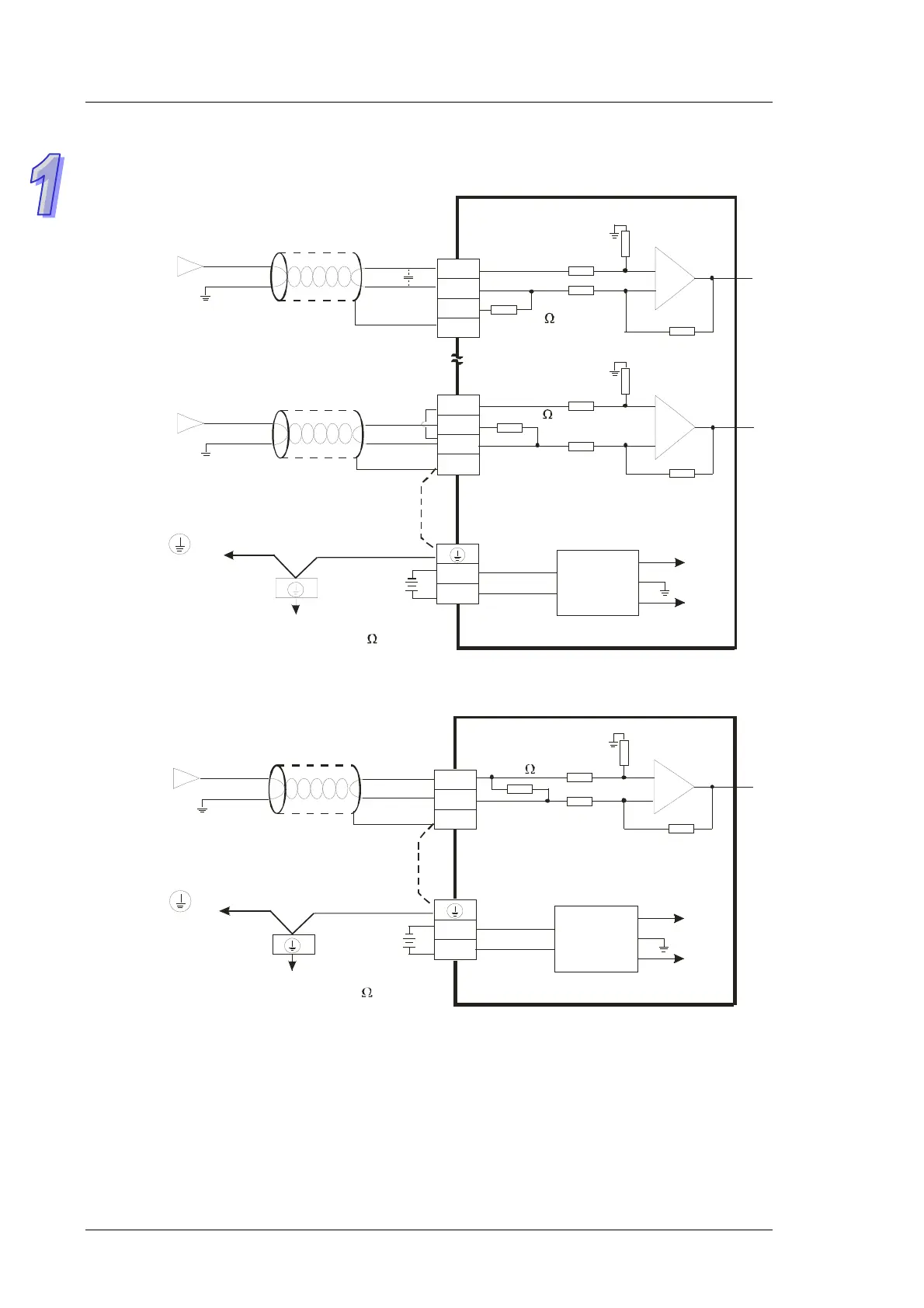
Wiring Analog Input Channels
TP70P-22XA1R
-10V~+10V
V0+
VI0-
CH0
-20mA~+20mA
V3+
I3+
VI3-
CH3
*3
*2
CH0
1M
CH3
AG
1M
1M
AG
1M
250
250
+15V
-15V
AG
0V
24V
FE
FE
DC24V
*5
*4
I0+
DC/DC
converter
Voltage input
Shielded cable*1
Shielded cable*1
Current input
Connected to on a
power supply module
System ground
Ground
(Impedance: Less than 100 )
TP70P-21EX1R
DC/DC
converter
Shielded cable*1
Current input
Connected to on a
power supply module
System ground
Ground
(Impedance: Less than 100 )
-20mA~+20mA
I0+
I0-
CH0
CH0
1M
AG
1M
250
+15V
-15V
AG
0V
24V
FE
DC24V
*5
*4
*1: Please isolate analog input cables from other power cables.
*2: If current is connected, the connection between V3+ and I3+ need to be a short circuit.
*3: If ripple voltage results in interference with the wiring, please connect a 0.1~0.47 μF and 25 V capacitor.
*4: If there is much noise, please connect the terminal FE to the ground terminal.
*5: Please connect the ground terminal on a power supply module and the analog input terminal FE to the
system ground, and then ground the system ground or connect the system ground to a distribution box.
 Loading...