TP70P Quick Start
1-12
1.8
Wiring
1.8.1
Wiring a Power Input Connector
The power supplied to TP70P is DC power. When users use TP70P, they have to note the following points.
Please connect wires to the terminals +24V and 0V. The power supplied to TP70P should be in the range
of 20.4 V DC to 28.8 V DC. If the voltage of the power supplied to TP70P is less than 20.4 V DC, TP70P
will stop running, and output devices will be off.
If a power cut is shorter than 10 milliseconds, TP70P will not stop running. If a short cut is long, or the
voltage of the power supplied to TP70P decreases, TP70P will stop running, and output devices will be off.
If power is restored after a power cut, TP70P will automatically resume running. (There are latching
auxiliary relays and retentive registers in TP70P. Users should use them carefully when they design a
program.)
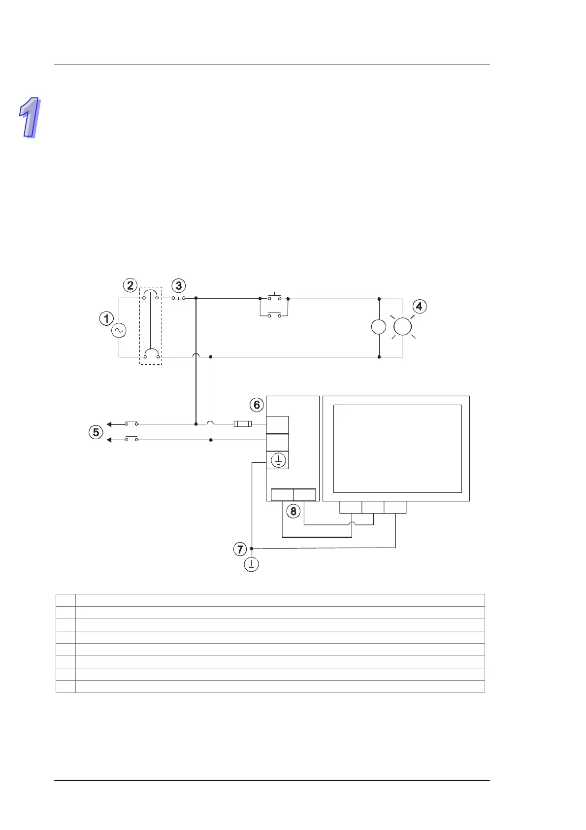
The power supplied to TP70P is DC power. A Delta power supply module (DVPPS02/DVPPS05) can be
used to supply power to TP70P. In order to protect DVPPS02/DVPPS05, users need to have the protection
circuit shown below.
24V
0V
AC
100~240V
50/60Hz
2A
DVPPS02
L
N
MC
TP70
24V
0V FE
AC power supply: 100~240 V AC, 50/60 Hz
Circuit breaker
Emergency stop: An emergency stop button can be used to cut off power when an emergency occurs.
Power indicator
AC load
2 A fuse
Ground (Impedance: Less than 100 Ω)
DC power supply: 24 V DC
 Loading...