TP70P Quick Start
1-16
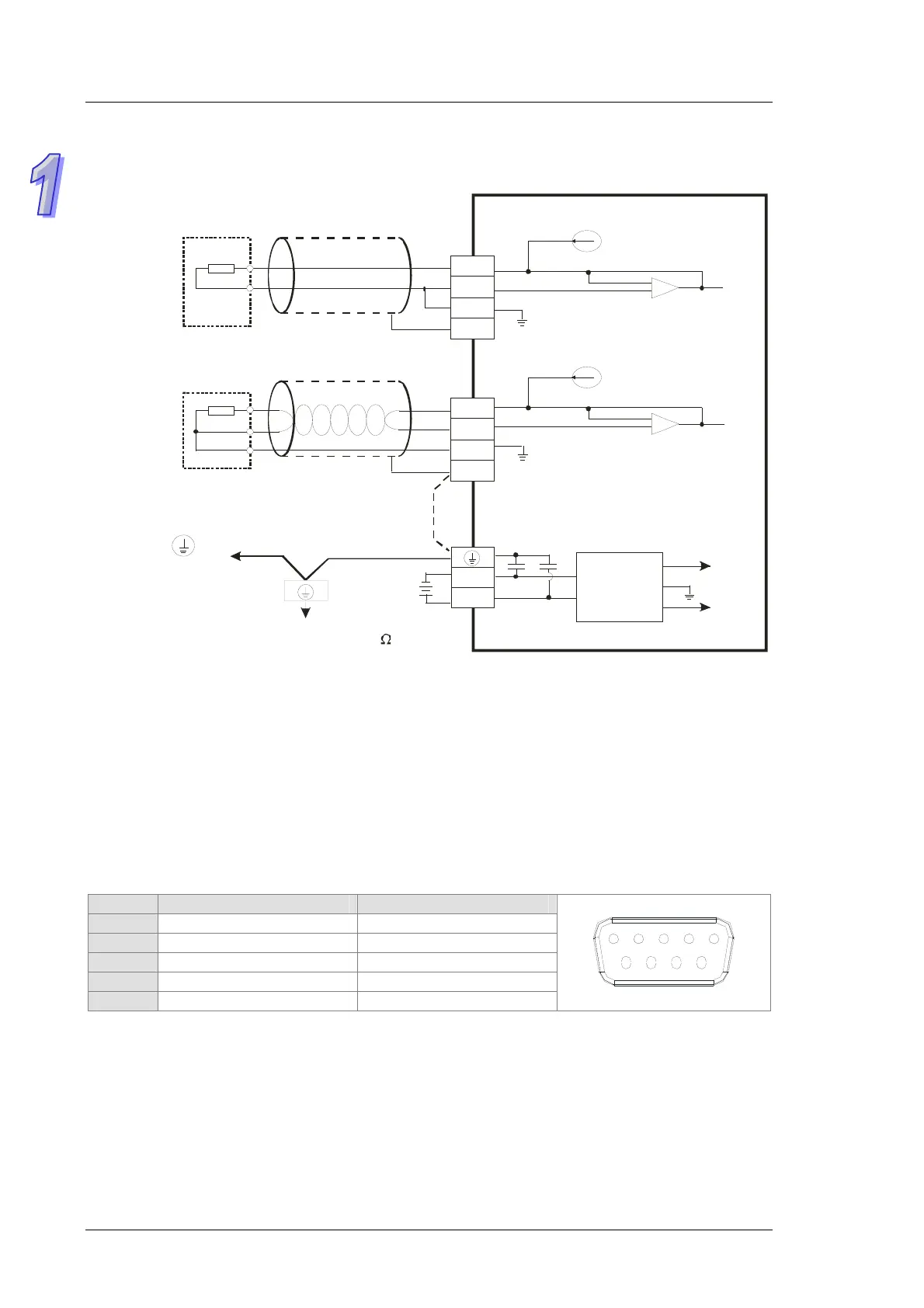
1.8.6
Wiring Temperature Measurement Input Terminals
TP70P-21EX1R
DC/DC
converter
Shielded cable*1
Connected to on a
power supply module
System ground
Ground
(Impedance: Less than 100 )
1.66mA (Ni100,Pi100,
resistor)
AG
AG
L3+
L3-
I3-
FE
L4+
L4-
I4-
FE
0V
24V
+15V
-15V
AG
*2
1.66mA (Ni100,Pt100,
resistor)
0~300
Ni100/Pt100
Ω
0~300
Nt100/Pt100
Ω
DC24V
*3
Two-wire
Three-wire
Shielded cable*1
*1: The cables connected to the input terminals should be cables or shielded twisted pair cables which can be
connected to temperature sensors, and should be kept separate from other power cables and cables which
may generate noise.
*2: If there is much noise, please connect the terminal FE to the ground terminal.
*3: Please connect FE on a power supply module and the temperature measurement input terminal FE to the
system ground, and then ground the system ground or connect the system ground to a distribution box.
*4: Please do not wire the terminal .
1.9
Definitions of the Pins in Communication Ports
TP70P-16TP1R, TP70P-21EX1R, TP70P-22XA1R, TP70P-32TP1R
Pin RS-485 (COM2) RS-485 (COM3)
5 GND GND
6 D+ N/C
7 D- N/C
8 N/C D+
9 N/C D-
12
3
45
67
89
 Loading...