Chapter 2 Writing Programs
2.2.1
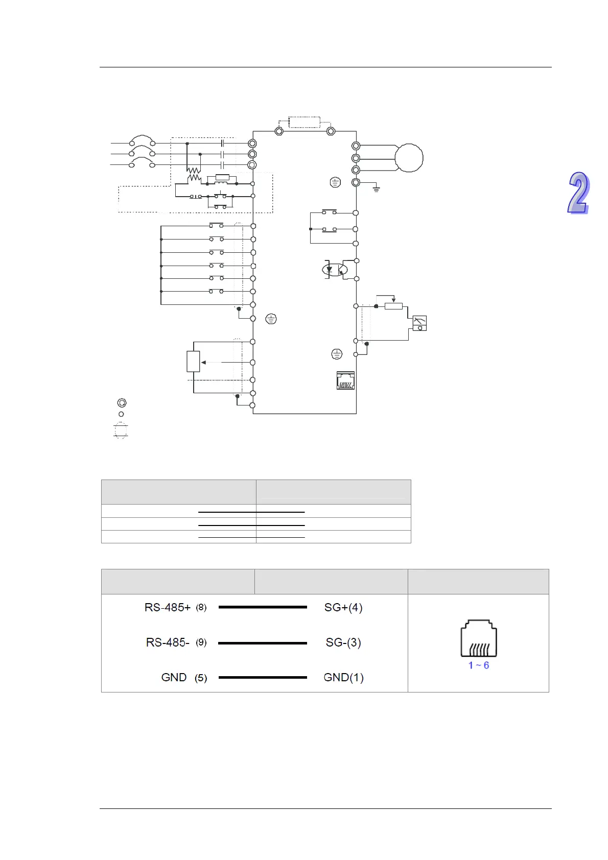
Wiring Diagram for a Delta VFD-M Series AC Motor Drive
U(T1)
V(T2)
W(T3)
M
3~
AC motor
MO1
MCM
Multi-function photocoupler output contact
Factory default: Indicating operation
48VDC 50mA
*
* Three-phase power can be input to a single phase model.
If it is a single phase, please select any two input power terminals in the main circuit power.
E
RA
RB
RC
Multi-function indication output contact
120VAC/250VAC, 5A
24VDC, less than 2.5A
Factory default: Indicating a malfunction
The specifications for the main
circuit terminal is M3.0.
Third ground
230 series: The impedance is less than 100 .Ω
460 series: The impedance is less than 10 .Ω
Stopping forward
rotation
Stopping backward
rotation
Multi-speed
command 1
Multi-speed
command 2
Multi-speed
command 3
Resetting
Common signal
M0
Factory default
M1
M2
M3
M4
M5
GND
AFM
GND
+
-
For adjustment
VR(1k )Ω
Analog output
DC 0~10V
Factory default: Output frequency
RS-485
serial
communication
61
←
RJ-11
1: 15V
2: GND
3: SG-
4: SG+
5: NC
6: For communication
Main circuit terminal
Control circuit terminal
Shielded lead
B1
B2
Brake resistor (optional)
R(L1)
S(L2)
T(L3)
NFB
R
S
T
SA
OFF
ON
MC
MC
RB
RC
Recommended
circuit used when
the power supply is
turned OFF by a faulty output
E
AVI
GND
Master frequency setting
Factory default: VR on the
digital keypad
Power for speed setting
+10V 10mA(MAX)
3
2
1
VR
Analog voltage
0~10VDC
VR: 3k~5kΩ
ACI
E
Analog current
4~20mA
※ Please refer to VFD-M User Manual for more information.
2.2.2
Wiring Diagram for External Terminals
TP70P series text panel
External I/O connector
VFD-M series AC motor drive
C0 GND
Y0 M0
Y1 M1
2.2.3
Wiring Diagram for Communication
TP70P
COM3 (RS-485)
Controller
RJ11 connector (RS-485)
Controller
Pins in an RJ11 connector
2-3
 Loading...