Chapter 3 Frequently Asked Questions and Answers
Step 2:
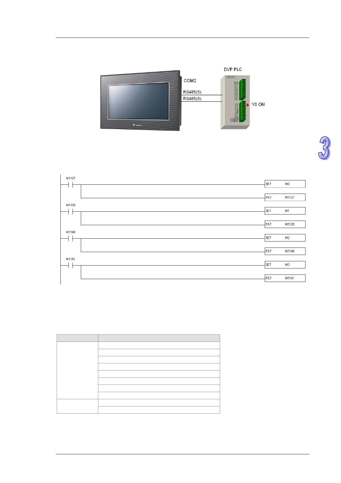
Connect COM2 to the two RS-485 wires connected to a DVP series PLC. When TP70P runs, Y0 on the
DVP series PLC is ON.
Step 3:
If communication error judgement is required, the program below can be added. If communication data
is transmitted normally, M0 will be ON. If a communication timeout occurs, M1 will be ON. If the data received is
incorrect, M2 will be ON. If parameters of an instruction are set incorrectly, M3 will be ON. Users can judge the
state of communication by means of these flags.
3.5 Setting COM3
【
Question
】
How to set COM3?
【
Answer
】
COM3 supports the text panel. After a driver is selected, COM3 can function as a master/slave
station. Users can set a communication format for COM3 in the
Basic Configuration
window in TPEditor. The
drivers supported by TP70P are shown in the table below. The setting of COM3 is described below.
Master/Slave Driver
Delta PLC
Delta Inverter VFD
Delta ASD AC Servo
Delta VFD ASCII Mode
Delta VFD RTU Mode
Delta Modbus ASCII
Delta Modbus RTU
Master
Modicon Modbus RTU Mode
Modbus Slave ASCII Mode
Slave
Modbus Slave RTU Mode
3-7
 Loading...