2. DISPLAY
S020-MXS4035A-3(FRONT)
No. M07047A009-1
◆製
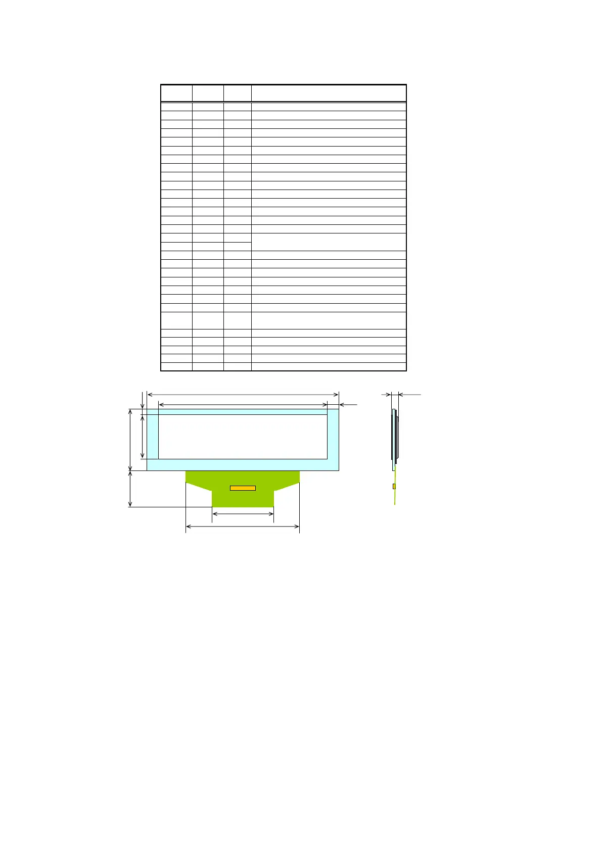
品概略図 External View of OLED Unit
◆製
品概要 Product Summar
◆I/Oインターフェース I/O Interfaces
端子番号 端子名 入出力
Pin No. Pin Name I/O
1 VSS P
2 VCC P
3 VCOMH P
4 VLSS P
5 CLS I
6 D7 I
7 D6 I
8 D5 I
9 D4 I
10 D3 I
11 D2 I
12 D1(SDIN) I
13
D0(SCLK) I
14
RD# I
15
WR# I
16
BS0 I
17
BSI I
18
D/C# I
19
CS# I
20
RES# I
21
VSS P
22
CL I
23
IREF O
24
NC -
26
VDD O
27
VCI P
28
VSL P
29
VLSS P
30
VCC P
*2: 25℃/点灯率30% Lighting Ratio 30% at 25℃
◆電気特性 Electrical Characteristics
Symbol Min Typ Max Unit
VCC - 16.0 - V
VCI 2.40 - 3.50 V
VDDIO 1.65 - 3.50 V
IH1 - 40.0 - mA
IDD1 - 0.21 - mA
IH2 - - 10 μA
IDD2 - - 60 μA
*3:VCC=16.0V、VCI=VDDIO=3.3V
Outline Specification of MXS4035(256x64dots) OLED UNIT
15.2(typ.)
0.342×0.333mm
99.2×30.4mm
データバス(シリアルデータ) Data Bus(Serial Data)
白
White
-
16
2.02(typ.)
インターフェイス Pin数
Number of Interface Pins
Pin
製品重量
Product Weight
mm
g
-
総厚 (偏光板有り)
Total of Thickness(With Polarizer)
mm
発光色
Color
-
階調
Gray Scale
-
ガラス基板外形(横×縦)
Substrate Size(WxH)
スタンバイモード ドライブ系電源電流
Drive System Power Current
on Standby Mode
単位
Unit
OLEDディスプレイユニット
OLED Display Unit
256×64
表示形態
Product Name
-
ドットマトリクス
Dot Matrix
品名
Product Name
-
ドット数(横×縦)
Number of Dots(W×H)
消費電流
Current
Consumption
(*3)
仕様
Specification
項目
Item
スタンバイモード ロジック系電源電流
Logic System Power Current
on Standby Mode
全点灯モード ロジック系電源電流
Logic System Power Current
on All-Dots-On Mode
cd/㎡
全点灯モード ドライブ系電源電流
Drive System Power Current
on All-Dots-On Mode
ドライブ系電源電圧
Drive System Power Voltage
ロジック系電源
Logic System Power Voltage
項目 Item
輝度(偏光板有り)
Luminance(With Polarizer)
項目 Item
電源電圧
Power
Voltage
インターフェイス系電源電圧
Interface System Power Voltage
ドットピッチ(横×縦)
Dot Pitch(WxH)
- 100 -
30
Parallel / Serial(SPI)
87.52×21.28(3.5inch)
アクティブエリア(横×縦)
Active Area Size(WxH)
インターフェイス
Interface
適合コネクタ
Connector
-
色度
Color Coordinates
- - 0.31,0.33
半減寿命 (*2)
The Time for Luminance to Decrease in Half
H - 70,000
-
陽極基準電位 Anode Reference Voltage
アナロググランド Analog System Ground
ドライブ系電源電圧 Drive System Power Voltage
書き込み Write
インターフェース選択端子
Select MCU Bus Interface Setting
内部ロジック電源 Internal Logic Power
ロジック系電源 Logic System Power Voltage
データ/コマンド選択 Select Data/Command
チップセレクト Chip Select
VDDIO
25
インターフェイス系電源電圧
Interface System Power Voltage
P
リセット Reset
機能
Function
データバス Data Bus
データバス Data Bus
データバス Data Bus
読み出し Read
データバス(シリアルクロック) Data Bus(Serial Clock)
データバス Data Bus
データバス Data Bus
データバス Data Bus
-
IRISO ELECTRONICS
9661S-30Y901(1.0mm pitch)
グランド GND
ドライブ系電源電圧 Drive System Power Voltage
陰極電源 Power Supply for Cathode Driver
アナロググランド Analog System Ground
VDDIO接続 Connect to VDDIO
基準電流 Reference Current Setting
グランド GND
VSS接続 Connect to VSS
*1:アクティブエリア Active Area
87.52(*1)
99.2
21.28
30.4
3.06
5.84
2.02
18.3
31.0
59.3
1. 仕様を予告なく変更させて頂く場合が御座いますので
ご了承下さい。
All specifications are subject to change without any advance notice.
2. 仕様は主要箇所のみ記載しております。
下記の詳細に関しては営業部門にお問い合わせ下さい。
The specifications show essential information only.
Please contact our sales department for the following details.
※フレキシ
ル基板の仕様はお客様のご要望にお応え致します。
Specifications of flexible printed circuits(FPC) are available
to meet customers' requirements.
※発光色に関しては各色取り揃えております。
Wide variety of color options are available.
※カスタムのご要望にもお応え致します。
Custom models are also available by customers' requirements.
この製品の内容は2011年6月現在のものです。
This product is as of June 2011.
注 意 / NOTE
東北パイオニア株式会社
OLED
事業部
〒
992-1128
山形県米沢市八幡原四丁目3146-7
TEL.0238-28-7853 FAX.0238-28-7885
TOHOKU PIONEER CORPORATION
OLED Business Unit
Hachimanpara, Yonezawa, Yamagata 992-1128, Japan
TEL.+81-238-28-7853 FAX.+81-238-28-7885
E-mail:el_eigyo_tpc@post.pioneer.co.jp
Homepage:http://pioneer.jp/topec/index.html
No. M07047A009-1
◆製
品概略図 External View of OLED Unit
◆製
品概要 Product Summar
◆I/Oインターフェース I/O Interfaces
端子番号 端子名 入出力
Pin No. Pin Name I/O
1 VSS P
2 VCC P
3 VCOMH P
4 VLSS P
5 CLS I
6 D7 I
7 D6 I
8 D5 I
9 D4 I
10 D3 I
11 D2 I
12 D1(SDIN) I
13
D0(SCLK) I
14
RD# I
15
WR# I
16
BS0 I
17
BSI I
18
D/C# I
19
CS# I
20
RES# I
21
VSS P
22
CL I
23
IREF O
24
NC -
26
VDD O
Characteristics
27
VCI P
28
VSL P
Unit Min Typ Max
29
VLSS P
30
VCC P
*2: 25℃/点灯率30% Lighting Ratio 30% at 25℃
◆電気特性 Electrical Characteristics
Symbol Min Typ Max Unit
VCC - 16.0 - V
VCI 2.40 - 3.50 V
VDDIO 1.65 - 3.50 V
IH1 - 40.0 - mA
IDD1 - 0.21 - mA
IH2 - - 10 μA
IDD2 - - 60 μA
*3:VCC=16.0V、VCI=VDDIO=3.3V
Outline Specification of MXS4035(256x64dots) OLED UNIT
15.2(typ.)
0.342×0.333mm
99.2×30.4mm
データバス(シリアルデータ) Data Bus(Serial Data)
白
White
-
16
2.02(typ.)
インターフェイス Pin数
Number of Interface Pins
Pin
製品重量
Product Weight
mm
g
-
総厚 (偏光板有り)
Total of Thickness(With Polarizer)
mm
発光色
Color
-
階調
Gray Scale
-
ガラス基板外形(横×縦)
Substrate Size(WxH)
スタンバイモード ドライブ系電源電流
Drive System Power Current
on Standby Mode
単位
Unit
OLEDディスプレイユニット
OLED Display Unit
256×64
表示形態
Product Name
-
ドットマトリクス
Dot Matrix
品名
Product Name
-
ドット数(横×縦)
Number of Dots(W×H)
消費電流
Current
Consumption
(*3)
仕様
Specification
項目
Item
スタンバイモード ロジック系電源電流
Logic System Power Current
on Standby Mode
全点灯モード ロジック系電源電流
Logic System Power Current
on All-Dots-On Mode
cd/㎡
全点灯モード ドライブ系電源電流
Drive System Power Current
on All-Dots-On Mode
ドライブ系電源電圧
Drive System Power Voltage
ロジック系電源
Logic System Power Voltage
項目 Item
輝度(偏光板有り)
Luminance(With Polarizer)
項目 Item
電源電圧
Power
Voltage
インターフェイス系電源電圧
Interface System Power Voltage
ドットピッチ(横×縦)
Dot Pitch(WxH)
- 100 -
30
Parallel / Serial(SPI)
87.52×21.28(3.5inch)
アクティブエリア(横×縦)
Active Area Size(WxH)
インターフェイス
Interface
適合コネクタ
Connector
-
色度
Color Coordinates
- - 0.31,0.33
半減寿命 (*2)
The Time for Luminance to Decrease in Half
H - 70,000
-
陽極基準電位 Anode Reference Voltage
アナロググランド Analog System Ground
ドライブ系電源電圧 Drive System Power Voltage
書き込み Write
インターフェース選択端子
Select MCU Bus Interface Setting
内部ロジック電源 Internal Logic Power
ロジック系電源 Logic System Power Voltage
データ/コマンド選択 Select Data/Command
チップセレクト Chip Select
VDDIO
25
インターフェイス系電源電圧
Interface System Power Voltage
P
リセット Reset
機能
Function
データバス Data Bus
データバス Data Bus
データバス Data Bus
読み出し Read
データバス(シリアルクロック) Data Bus(Serial Clock)
データバス Data Bus
データバス Data Bus
データバス Data Bus
-
IRISO ELECTRONICS
9661S-30Y901(1.0mm pitch)
グランド GND
ドライブ系電源電圧 Drive System Power Voltage
陰極電源 Power Supply for Cathode Driver
アナロググランド Analog System Ground
VDDIO接続 Connect to VDDIO
基準電流 Reference Current Setting
グランド GND
VSS接続 Connect to VSS
*1:アクティブエリア Active Area
87.52(*1)
99.2
21.28
*1
30.4
3.06
5.84
18.3
31.0
59.3
1. 仕様を予告なく変更させて頂く場合が御座いますので
ご了承下さい。
All specifications are subject to change without any advance notice.
2. 仕様は主要箇所のみ記載しております。
下記の詳細に関しては営業部門にお問い合わせ下さい。
The specifications show essential information only.
Please contact our sales department for the following details.
※フレキシ
ル基板の仕様はお客様のご要望にお応え致します。
Specifications of flexible printed circuits(FPC) are available
to meet customers' requirements.
※発光色に関しては各色取り揃えております。
Wide variety of color options are available.
※カスタムのご要望にもお応え致します。
Custom models are also available by customers' requirements.
この製品の内容は2011年6月現在のものです。
This product is as of June 2011.
注 意 / NOTE
東北パイオニア株式会社
OLED
事業部
〒
992-1128
山形県米沢市八幡原四丁目3146-7
TEL.0238-28-7853 FAX.0238-28-7885
TOHOKU PIONEER CORPORATION
OLED Business Unit
Hachimanpara, Yonezawa, Yamagata 992-1128, Japan
TEL.+81-238-28-7853 FAX.+81-238-28-7885
E-mail:el_eigyo_tpc@post.pioneer.co.jp
Homepage:http://pioneer.jp/topec/index.html
86
 Loading...