© 2014 Digi International Inc. 11
XBee/XBee-PRO
®
DigiMesh 2.4 User Manual
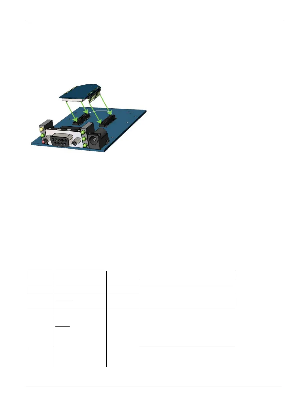
Mounting Considerations for the XBee/XBee-PRO DigiMesh 2.4
The XBee/XBee-PRO
®
DigiMesh 2.4 RF Module (through-hole) is designed to be mounted into a
receptacle (socket) and does not require any soldering when mounting it to a board. The
development kits contain RS-232 and USB interface boards that use two 20-pin receptacles to
receive modules.
XBee/XBee-PRO DigiMesh 2.4 RF module mounting to an RS-232 Interface Board.
The receptacles on Digi development boards are manufactured by Century Interconnect and
Samtec. Several other manufacturers provide comparable mounting solutions; However, Digi
currently uses the following receptacles:
• Through-hole single-row receptacles-Samtec P/N: MMS-110-01-L-SV (or equivalent)
• Surface-mount double-row receptacles-Century Interconnect P/N: CPRMSL20-D-0-1 (or
equivalent)
• Surface-mount single-row receptacles-Samtec P/N: SMM-110-02-SM-S
Note: Digi recommends that you print an outline of the module on the board to indicate the
correct orientation for mounting the module.
XBee/XBee-PRO DigiMesh 2.4 Pin Signals
The following table shows the XBee/XBee-PRO
®
DigiMesh 2.4 RF Module pin signals and
descriptions:
Pin # Name Direction Description
1 Vcc - Power supply
2 DOUT Output UART data out
3
DIN/
CONFIG
Input UART data in
4 DIO12 Either Digital I/O 12
5 RESET
Input/Open
drain output
Module reset (reset pulse must be at least
100 us. This must be driven as an open
drain/collector. The module will drive this
line low when a reset occurs. This line
should never be driven high.)
6 PWM0/RSSI/DIO10 Either
PWM output 0 / RX signal strength
indicator / Digital I/O
7 PWM/DIO11 Either PWM output 1 / Digital I/O 11

 Loading...


