© 2014 Digi International Inc. 39
XBee/XBee-PRO
®
DigiMesh 2.4 User Manual
If the IS command is issued from AT command mode, then a carriage return delimited list will be
returned containing the above-listed fields. If the command is issued via an API frame, the
module returns an AT command response API frame with the IO data included in the command
data portion of the packet.
XBee Periodic I/O Sampling
Periodic sampling allows an XBee-PRO module to take an I/O sample and transmit it to a remote
device at a periodic rate. The periodic sample rate is set by the IR command. If IR is set to 0,
periodic sampling is disabled. For all other values of IR, data is disabled after IR milliseconds
have elapsed and transmitted to a remote device. The DH and DL commands determine the
destination address of the IO samples. Only devices with API mode enabled will send IO data
samples out their UART. Devices not in API mode will discard received IO data samples.
A module with sleep enabled transmits periodic I/O samples at the IR rate until the ST time
expires and the device can resume sleeping. See the sleep section for more information.
XBee Digital I/O Change Detection
Modules can be configured to transmit a data sample immediately whenever a monitored digital
I/O pin changes state. The IC command is a bitmask that is used to set which digital I/O lines
should be monitored for a state change. If one or more bits in IC is set, an I/O sample is
transmitted as soon as a state change is observed in one of the monitored digital I/O lines. The
figure below shows how edge detection can work with periodic sampling.
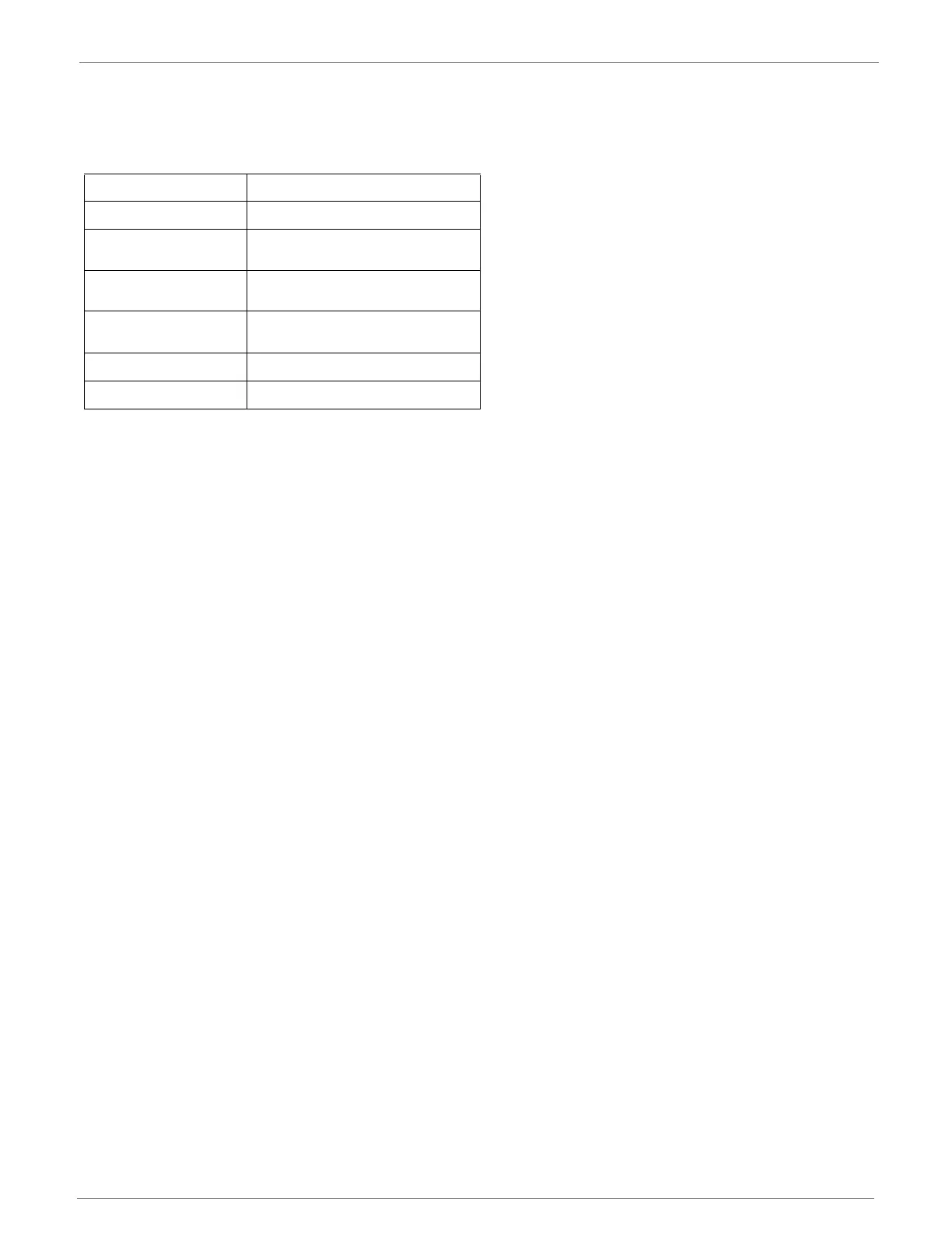
Example Sample AT Response
0x01\r [1 sample set]
0x0C0C\r
[Digital Inputs: DIO 2, 3, 10, 11
enabled]
0x03\r
[Analog Inputs: A/D 0, 1
enabled]
0x0408\r
[Digital input states: DIO 3, 10
high, DIO 2, 11 low]
0x03D0\r [Analog input ADIO 0= 0x3D0]
0x0124\r [Analog input ADIO 1=0x120]