© 2014 Digi International Inc. 18
XBee/XBee-PRO
®
DigiMesh 2.4 User Manual
horizontal line over signal name).
XBee Serial Data
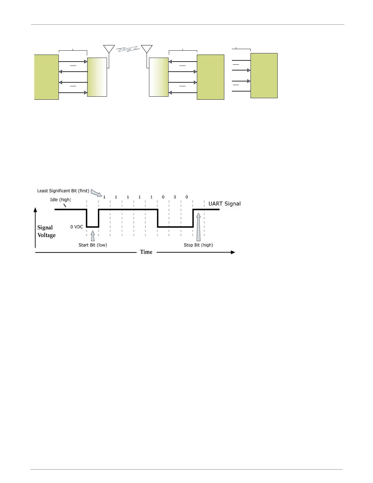
Data enters the module UART through the DIN (pin 3) as an asynchronous serial signal. The
signal will idle high when no data is being transmitted.
Each data byte consists of a start bit (low), 8 data bits (least significant bit first) and a stop bit
(high). The following figure illustrates the serial bit pattern of data passing through the module.
UART data packet 0x1F (decimal number “31”) as transmitted through the RF module. Example data for-
mat is 8-N-1 (bits - parity - # of stop bits)
The module UART performs tasks such as timing and parity checking, which is needed for data
communications. Serial communications depend on the two UARTs to be configured with
compatible settings (baud rate, parity, start bits, stop bits, data bits).
XBee Serial Buffers
The XBee-PRO modules maintain buffers to collect received serial and RF data, which is
illustrated in the figure below. The serial receive buffer collects incoming serial characters and
holds them until they can be processed. The serial transmit buffer collects data that is received
via the RF link that will be transmitted out the UART.
Microcontroller Microcontroller
XBee
Module
XBee
Module
CMOS Logic (3.0-3.6V)
DOUT (data out)
DIN (data in)
CTS
RTS
CMOS Logic (3.0-3.6V)
DOUT (data out)
DIN (data in)
CTS
RTS
Microcontroller
XBee
Module
XBee
Module
CMOS Logic (3.0-3.6V)
DOUT (data out)
DIN (data in)
CTS
RTS
CMOS Logic (3.0-3.6V)
DOUT (data out)
DIN (data in)
CTS
RTS

 Loading...


