© 2014 Digi International Inc. 37
XBee/XBee-PRO
®
DigiMesh 2.4 User Manual
XBee/ XBee-PRO DigiMesh 2.4 I/O Line
Monitoring
I/O Samples
The XBee modules support both analog input and digital IO line modes on several configurable
pins.
Queried Sampling
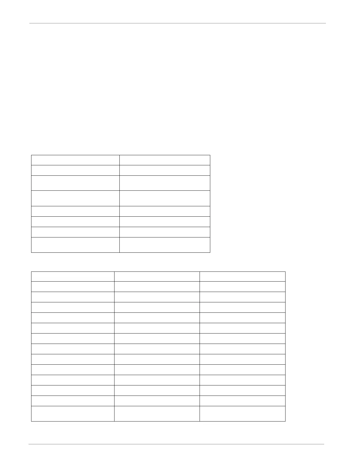
Parameters for the pin configuration commands typically include the following:
Setting the configuration command that corresponds to a particular pin will configure the pin:
Pin Command Parameter Description
0 Unmonitored digital input
1
Reserved for pin-specific alternate
functionalities.
2
Analog input (A/D pins) or PWM
output (PWM pins)
3 Digital input, monitored.
4 Digital output, default low.
5 Digital output, default high.
6-9
Alternate functionalities, where
applicable.
Module Pin Names Module Pin Number Configuration Command
CD / DIO12 4 P2
PWM0 / RSSI / DIO10 6 P0
PWM1 / DIO11 7 P1
DTR / SLEEP_RQ / DIO8 9 D8
AD4 / DIO4 11 D4
CTS / DIO7 12 D7
ON_SLEEP / DIO9 13 D9
ASSOC / AD5 / DIO5 15 D5
RTS / DIO6 16 D6
AD3 / DIO3 17 D3
AD2 / DIO2 18 D2
AD1 / DIO1 19 D1
AD0 / DIO0 / Commissioning
Button
20 D0

 Loading...


