© 2014 Digi International Inc. 15
XBee/XBee-PRO
®
DigiMesh 2.4 User Manual
XBee/XBee-PRO
®
DigiMesh 2.4 Electrical Characteristics
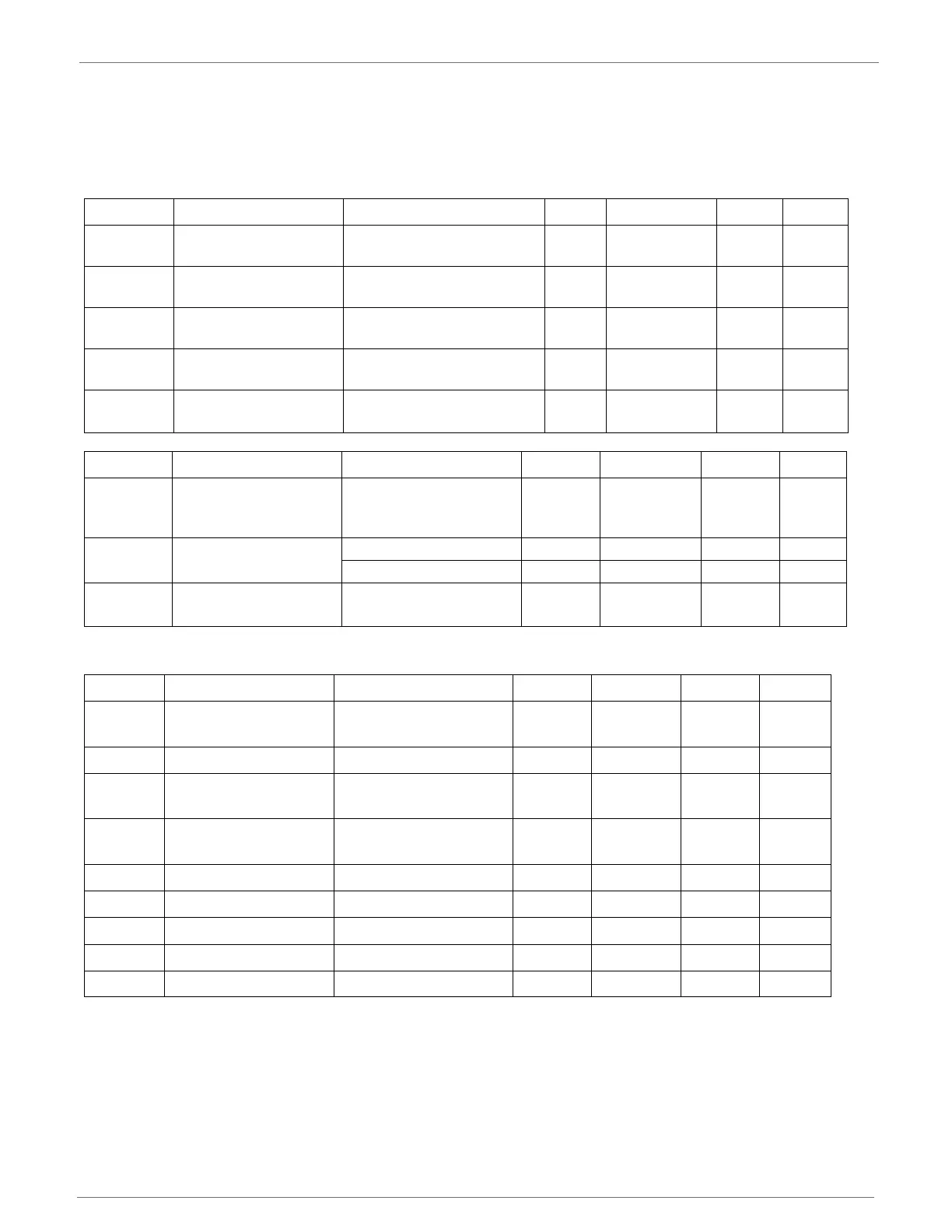
The following table displays the electrical voltage parameters of the XBee/XBee-PRO
®
DigiMesh
2.4 RF Module:
1 Maximum electrical operating range, not valid conversion range
1 All ACCURACY numbers are based on processor and system being in WAIT state (very little activity and no IO switching) and that adequate low-pass
filtering is present on analog input pins (filter with 0.01
F to 0.1 F capacitor between analog input and V
REFL
). Failure to observe these guidelines
may result in system or microcontroller noise causing accuracy errors which will vary based on board layout and the type and magnitude of the activity.
Data transmission and reception during data conversion may cause some degradation of these specifications, depending on the number and timing
of packets. It is advisable to test the ADCs in your installation if best accuracy is required.
2 R
AS
is the real portion of the impedance of the network driving the analog input pin. Values greater than this amount may not fully charge the input
circuitry of the ATD resulting in accuracy error.
3 Analog input must be between V
REFL
and V
REFH
for valid conversion. Values greater than V
REFH
will convert to $3FF.
4 The resolution is the ideal step size or 1LSB = (V
REFH
–V
REFL
)/1024
Symbols Parameter Condition Min Typical Max Units
V
IL
Input low voltage All digital inputs - -
0.2 *
VCC
V
V
IH
Input high voltage All digital inputs
0.8 *
VCC
- - V
V
OL
Output low voltage
I
OL
= 2 mA, VCC >= 3.0 V
--
0.18*VC
C
V
V
OH
Output high voltage
I
OH
= 2 mA, VCC >= 3.0 V
0.82*V
CC
--V
II
IN
Input leakage current
V
IN
= VCC or GND, all
inputs, per pin
-- 0.5
A
Symbol Parameter Condition Min Typical Max Units
V
REFH
VREF-analog-to-digital
converter reference
range
2.08 -
V
DDAD
V
I
REF
VREF-reference supply
current
Enabled - 200 -
A
Disabled or sleep mode - < 0.01 0.02
A
V
INDC
Analog input voltage
V
SSAD
-
0.3
-
V
SSAD
+
0.3
V
Symbol Parameter Condition Min Typical Max Units
R
AS
Source impedance at
input
2
-- 10k
V
AIN
Analog input voltage
3
V
REFL
V
REFH
V
RES
Ideal resolution (1
LSB)
4
2.08V > V
DDAD
> 3.6V
2.031 3.516 mV
DNL
Differential non-
linearity
5
- ±0.5 ±1.0 LSB
INL
Integral non-linearity
6
- ±0.5 ±1.0 LSB
E
ZS
Zero-scale error
7
- ±0.4 ±1.0 LSB
F
FS
Full-scale error
8
- ±0.4 ±1.0 LSB
E
IL
Input leakage error
9
- ±0.05 ±5.0 LSB
E
TU
Total unadjusted error - ±1.1 ±2.5 LSB

 Loading...


