© 2014 Digi International Inc. 12
XBee/XBee-PRO
®
DigiMesh 2.4 User Manual
Note:
• Signal direction is specified with respect to the module
• Module includes a 50 k
pull-up resistor attached to RESET
• Several of the input pull-ups can be configured using the PR command
• Unused pins should be left disconnected
Recommended Pin Connections for XBee/XBee-PRO DigiMesh 2.4
The only required pin connections are VCC, GND, DOUT and DIN. To support serial firmware
updates, VCC, GND, DOUT, DIN, RTS, and DTR need to be connected.
All unused pins need to be left disconnected. All inputs on the radio can be pulled high with
internal pull-up resistors using the PR software command. No specific treatment is needed for
unused outputs.
Other pins can be connected to external circuitry for convenience of operation including the
Associate LED pin (pin 15) and the commissioning button pin (pin 20). The Associate LED pin will
flash differently depending on the state of the module, and a pushbutton attached to pin 20 can
enable various deployment and troubleshooting functions without having to send UART
commands.
If analog sampling is desired, attach the VRef pin (pin 14) to a voltage reference.
Note:
• Minimum pin connections on the XBee/XBee-PRO
2.4 DigiMesh: VCC, GND, DOUT & DIN
• Minimum connections on the XBee/XBee-PRO
DigiMesh 2.4 for updating firmware: VCC, GND,
DOUT, DIN, RTS & DTR
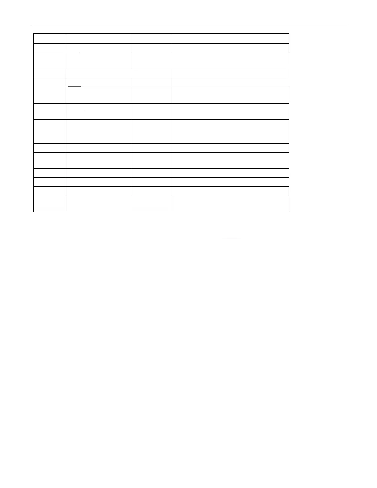
8 [reserved] - Do not connect
9
DTR
/ SLEEP_RQ/
DIO8
Either Pin sleep control line or Digital I/O 8
10 GND - Ground
11 AD4/DIO4 Either Analog input 4 or Digital I/O 4
12
CTS/
DIO7
Either Clear-to-send flow control or Digital I/O 7
13
ON/
SLEEP
Output Module Status Indicator or Digital I/O 9
14 VREF -
This line must be connected if analog I/O
sampling is desired. Must be between 2.6
V and Vcc.
15 Associate / DIO5/AD5 Either Associated indicator, Digital I/O 5
16
RTS/
DIO6
Either
Request-to-send flow control, Digital I/O
6
17 AD3 / DIO3 Either Analog input 3 or Digital I/O 3
18 AD2 / DIO2 Either Analog input 2 or Digital I/O 2
19 AD1 / DIO1 Either Analog input 1 or Digital I/O 1
20
AD0 / DIO0 /
Commissioning Button
Either
Analog input 0, Digital I/O 0, or
Commissioning button
Pin # Name Direction Description

 Loading...


