Operation Overview
Eaton ePDU G3 Operation Manual P-164000277—Rev 1 www.eaton.com/ePDU 32
Outlets and Circuit Breakers
A variety of outlet types are available for the Eaton ePDUs. Each ePDU model has a specific configuration of
outlets.The configuration can be standard or customized to suit your needs.
The outlets are grouped in sets called sections. Sections are preset grou
ps of individual outlets that you can
identify and monitor through the interfaces that are available with your particular type of ePDU.
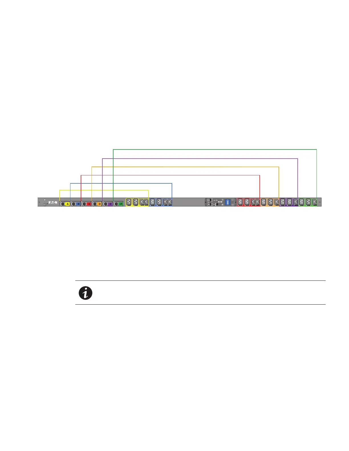
The outlets are color-coded and labeled, and if the model
has circuit breakers, the circuit breakers that are
associated with the outlets have corresponding labels (see Figure 29). (The “circuit breaker tripped” status is
not reported.)
Outlets and sections of outlets can be managed through the Web Interface (see “Groups” on page 104,
“Outlets” on page 105, and “User-Defined Group Definition” on page 113 ). You can see measurement readings
usin
g the local LCD interface.
A
1
A
2
A3 A4
B
1
B
2
B3 B4
C
1
C
2
C3 C4
D
1
D
2
D3
E
1
E
2
E3
F
1
F
2
F3
CB A
CB B
CB C
CB D
CB E
CB F
A1, A2, A3, A4
B1, B2, B3, B4
C1, C2, C3, C4
D1, D2, D3
E1, E2, E3
F1, F2, F3
Figure 29. Outlet Groups and Circuit Breakers
Ports, Operation Buttons and LED Status Indicators
The Eaton ePDUs include communication and serial ports (also used for environmental monitoring), operation
buttons, and status LEDs (see Figure 30). The ePDU front panel includes communication and monitoring ports,
LED st
atus indicators, and operation buttons. The ports and the associated LED indicators are described in the
following Table 4.
NOTE At startup, check the LED status display colors on the communication and
monitoring ports to ensure that they are operating correctly.
 Loading...


