Page 13-8
Effective 10/02For more information visit: www.cutler-hammer.eaton.comIL17562BH04
13.5 Application Considerations
13.5.1 Mode 1 and Mode 2 Output Contacts
The outputs of the MP-3000 relay can be configured in either mode 1
or mode 2 operation. Refer to sections 5.12.1 and 6.2.2 for more
information on the functionality of mode 1 and 2.
Upon removal of the relay inner chassis from the case, all contacts will
be disconnected unless the spare self-shorting contact is used as
described in Section 13.5.2.
13.5.2 Use of Spare Self-Shorting Contact
The MP-3000 drawout case provides a spare self-shorting contact on
terminals 29 and 30 (refer to Figure 13.4). This contact may be used
for continuous motor operation with the relay inner chassis removed
from the case while in mode 1 setting. It can also provide a protection
out of service when the relay is removed from the case.
Continuous Motor Operation
To provide for continuous motor operation when the relay is removed
simply set the relay trip output to Mode 1 operation and wire accord-
ingly. Wire terminals 29 and 30 in parallel with the normally closed trip
contacts terminals 54 and 56. Figure 13.5 shows this optional wiring
configuration.
This feature is not recommended for Mode 2 operation.
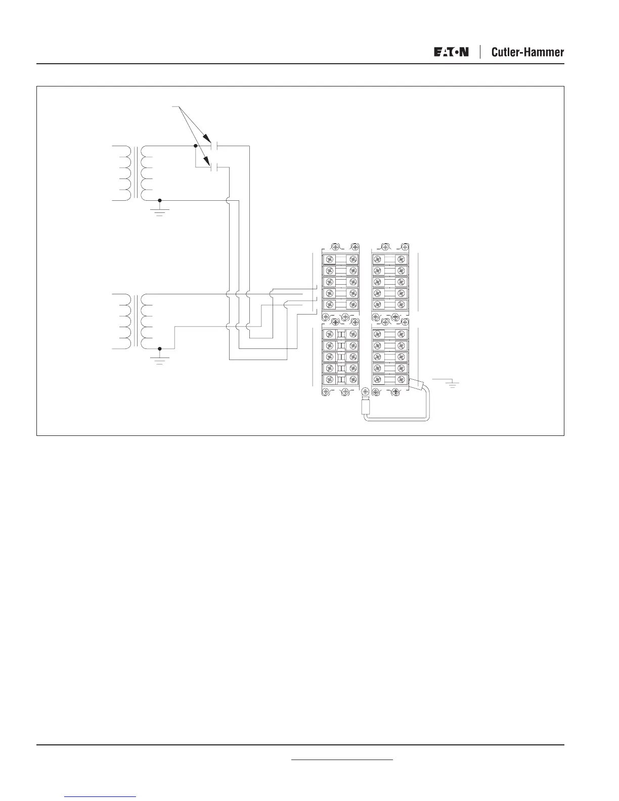
Fig. 13.7b MP-3000 Drawout Alternatives for Discrete Input Wiring
Relay Out of Service Alarm
The spare self-shorting contact may be connected to provide a relay
out of service alarm simply by wiring terminals 29 and 30 to an alarm
or annunciation panel. Proper control voltage must be supplied for the
alarm. When the relay is removed from its case, the self-shorting
terminals 29 and 30 will close. When the relay inner chassis is
reinstalled, the contact opens and the alarm is removed. Note that
this alarm can only be reset when the relay is installed in its case.
13.5.3 Armed/Disarmed Operation
The ARMED/DISARMED feature is most useful when the relay is fitted
in the optional drawout case. This feature blocks operation of the trip
output contacts but not the protection displays. This permits the
insertion of the relay without risk of tripping a critical motor due to
improper setting. The relay will provide relay alarm and trip status
indication. If this occurs upon insertion, the user has the option to
review applicable protection settings to verify they are correct. Refer
to sections 5.12.18 and 9.2.7 for more information on the proper
application and considerations of the ARM/DISARM feature.
NOTE: The relay must be placed back into the ARMED mode before
completing the installation. Failure to do so will disable the
motor protection and may result in serious motor and
equipment damage.
TRANSFORMER
CONTROL POWE
R
OR PUSHBUTTONS
INPUT CONTACTS
120 Va
c
120 Vac
REMOTE CONTACT
WETTING SUPPLY
or
240 Vac
ONL
Y
28
30
27
29
26
25
24
22
23
21
20
19
15 16
18
17
14
13
12
11
57
59
58
60
55 56
53
51
54
52
NON-CURRENT
CARRYIN
G GND
49 50
4645
47 48
43
44
41
42
 Loading...


