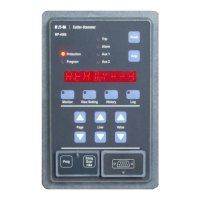
For more information visit: www.cutler-hammer.eaton.com
Page 11-1
Effective 10/02 IL17562BH04
SECTION 11—TESTING
11.0 General
The MP-3000 requires no maintenance. Do not remove the rear cover.
In most applications, normal cycles of use will demonstrate that the
relay is functioning properly. Use the following procedures for bench
checkout, or for verification of inputs and outputs that haven’t been
observed to function for one year or more. Users with normally trouble
free applications should check the alarm relay, and the annunciator to
which it is connected, at least annually.
11.1 What to test
The MP-3000 microprocessor routinely checks most of its own
electronics, plus program memory and the writable, nonvolatile data
storage memory. If it detects malfunctions, it reports specific
messages, and has settings to alarm the user and/or trip the motor as
desired. See Setting P12L16 in Table 4.3 and Section 5.12.16.
It is neither necessary nor beneficial to test individual functions of a
multifunction microprocessor relay for maintenance purposes. All
functions are performed by the same microprocessor electronics. It is
important only to make sure the settings are correct (use View Setting
mode any time), and to confirm that the inputs and outputs are working
with the application wiring.
To test the MP-3000 inputs and outputs, use the SP TEST page in the
Program mode. Refer to Sections 5.0 and 5.13 and to Table 4.3 for
details on using the Program mode to activate test settings P13L1 to
P13L8.
11.2 Tests on a Running Motor
In order to use any of the test settings on a running motor, the relay
must be set to allow programming while running. See STOP PGM
versus RUN PGM in Section 5.12.6 and Setting P12L6.
To test the trip output relay, the motor must be stopped in any case.
An attempt to test this while the motor runs will bring an ILLEGAL
message.
All other inputs and outputs can be tested while the motor runs.
DANGER
USING THE TEST SETTINGS WILL CHANGE THE STATE OF
OUTPUTS, REGARDLESS OF THE FUNCTIONS NORMALLY
OPERATING THOSE OUTPUTS. UNLESS TESTING IS URGENT,
WAIT UNTIL THE MOTOR IS STOPPED TO RUN TESTS. IF THE
MOTOR IS RUNNING, MAKE SURE THAT CHANGING THE OUTPUT
STATE WILL NOT CREATE A DANGEROUS SITUATION IN THE
MOTOR, STARTER, OR PROCESS.
11.3 Verifying Current Inputs
If the motor current readings were checked at the time of commission-
ing as described in Section 7, it is often adequate just to periodically
observe the motor load current readings during normal motor opera-
tion. Use the phase current values on the MONT I page of the Monitor
mode, or check values by remote communications. A clip-on ammeter
can also be used, but allow tolerance for errors in the clip-on Ct and in
the main Cts of the motor starter.
11.4 Bench Test of Current Inputs
Use a 3-phase source or relay test set to simulate motor load current;
check correctness of readings considering the scaling of the PCT and
GCT Ct ratio settings P1L5 and P1L6.
If a 3-phase source is not available, use the single-phase test mode of
the MP-3000. Set P13L1 to 1 PHASE. A single current around 3.5 to 4
A can be applied to all four Ct inputs, daisy-chained in series; observe
the metered values considering PCT and GCT.
WARNING
BE SURE TO RETURN SETTING P13L1 TO 3 PHASE BEFORE
RETURNING THE RELAY TO SERVICE. ALL PROTECTION FUNC-
TIONS THAT CHECK PHASE BALANCE OR SEQUENCE ARE
DISABLED IN 1 PHASE TEST MODE. SEEING THE DISPLAY
READY —1 IN THE MOTOR STATE MODE WHEN THE MOTOR IS
STOPPED IS A WARNING THAT THE SETTING IS AT 1 PHASE. THE
CORRECT DISPLAY IS READY —3.
11.5 Testing the Trip Relay
Stop the motor. The test is blocked if the motor is running. Enter
Program mode, go to test setting P13L2. The trip relay contacts
(terminals 11 through 13) can be monitored for proper operation, or
observe the controlled-circuit operation. Refer to Figure 6.5 for rear
panel terminal layout. To use this function:
• Determine whether the MP-3000 trip relay is configured for MODE 1
or MODE 2 operation - see SYSTEM Page Setting P12L1.
• If MODE1, the trip relay is normally de-energized. Set up for the test
by selecting TRP ENER in P13L2.
• If MODE 2, the trip relay is normally energized. Set up for the test by
selecting TRP DENR in P13L2.
• Push the Reset button to test the relay. The Trip LED also lights.
Release the button to revert to the prior output state.
11.6 Testing the Alarm Relay
Use setting P13L3. The procedure is the same as for the trip relay test.
Press the Reset pushbutton to light the Alarm LED and activate the
alarm contacts (terminals 17 through 19). If the MP-3000 is set for RUN
PGM, this output can be tested while the motor runs.
11.7 Testing the AUX1 Relay
Use setting P13L4. The procedure is the same as for the trip relay test.
Press the Reset pushbutton to light the Aux 1 LED and activate the Aux
1 contacts (terminals 14 through 16). If the MP-3000 is set for RUN
PGM, this output can be tested while the motor runs.
11.8 Testing the AUX2 Relay
Use setting P13L5. The procedure is the same as for the trip relay test.
Press the Reset pushbutton to light the Aux 2 LED and activate the Aux
2 contacts (terminals 1 through 3). If the MP-3000 is set for RUN PGM,
this output can be tested while the motor runs.
11.9 Testing the Analog Output
To test the 4-20 mA analog transducer output at terminals 24 and 25,
use P13L6. Set the test output current level to be 4, 12, or 20 mA.
Press the Reset button to force the selected test output current;
release to return to the normal measurement-driven output.
 Loading...


