12
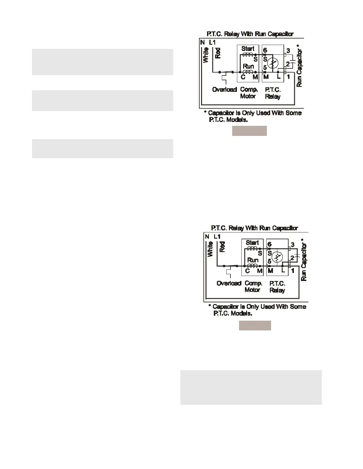
Compressor Start Circuit
When the compressor circuit is first energized, the solid
state relay has low resistance (3-12 ohms), and both the
run and start windings are energized to start the
compressor. The run capacitor
1
is being bypassed by
the relay, and it has a minor function during compressor
starting (See Figure C3).
Compressor Run Circuit
When the self-heating solid state relay has reached
sufficient temperature, it will abruptly change from low
resistance (3-12 ohms) to very high resistance (10-20K
ohms) and, in effect, switches off the start windings.
The relay no longer shunts the run capacitor. The run
capacitor is now in series with the start windings. The
only purpose of the run capacitor is to improve
compressor operating efficiency, which it does by cor-
recting the power factor of the compressor motor (See
Figure C4).
Figure C4
7. If ohm readings are out of range, install new
Starter/Overload Assembly.
NOTE: The Overload Protector is built into the
Starter Overload Assembly. It cannot be read
independently from the Starter.
8. Reverse this procedure to re-assemble.
NOTE: When replacing leads to the PTC Relay,
ensure the locking tabs snap back into the terminal.
Run Capacitor
The run capacitor has permanently attached terminals
which are connected to relay terminals 2 and 3.
To Check/Replace The Run Capacitor
1. Disconnect electrical supply to refrigerator.
2. Remove bale wire holding relay to compressor.
2. Use small, flat-bladed screwdriver to disconnect
leads to relay assembly.
3. Use flat-bladed screwdriver and gently pry
capacitor from relay assembly.
4. Discharge capacitor by shorting across terminals
with 500K (1 watt) resistor for one minute.
5. Use ohmmeter set on the “Ohms times 1000”
scale (if available), to check resistance across
capacitor wire terminals.
• The needle should jump towards zero ohms
and quickly move back to infinity.
• If the needle does not move, the capacitor is
open.
• If the needle reads a constant value at or near
zero ohms, the capacitor is shorted out.
• If the needle jumps toward zero and then
moves back to constant high resistance (not
infinity), the capacitor has a high resistance
leak.
6. If ohm readings are out of range, replace capacitor.
7. Reverse procedures to re-assemble.
Figure C3
NOTE: Some models are not equipped with a Run
capacitor
COMPRESSOR OPERATING CHARACTERISTICS
• When the compressor electrical circuit is energized,
the start winding current causes the relay to heat
and switch off the start winding circuit.
NOTE: The relay will switch off the start winding
circuit even though the compressor has not started
(as when attempting to re-start after momentary
power interruption).
• The overload protector is designed and calibrated
to open the compressor electrical circuit with locked
rotor run winding current only.
 Loading...