22
Defrost Control
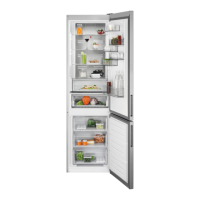
Two types of defrost controls are used; a timer system
(See Figure 20) and an Adaptive Defrost Control (ADC)
(See figure 21).
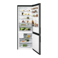
On models with a mechanical timer, the evaporator fan
motor is controlled by a third switch mounted on the
damper control. (See Figure 22.)
Figure 22
Damper Control for Timer Models
Damper Switch
(Bottom Switch)
Damper Motor Switch
Damper
Motor
Damper
Fan Motor Switch
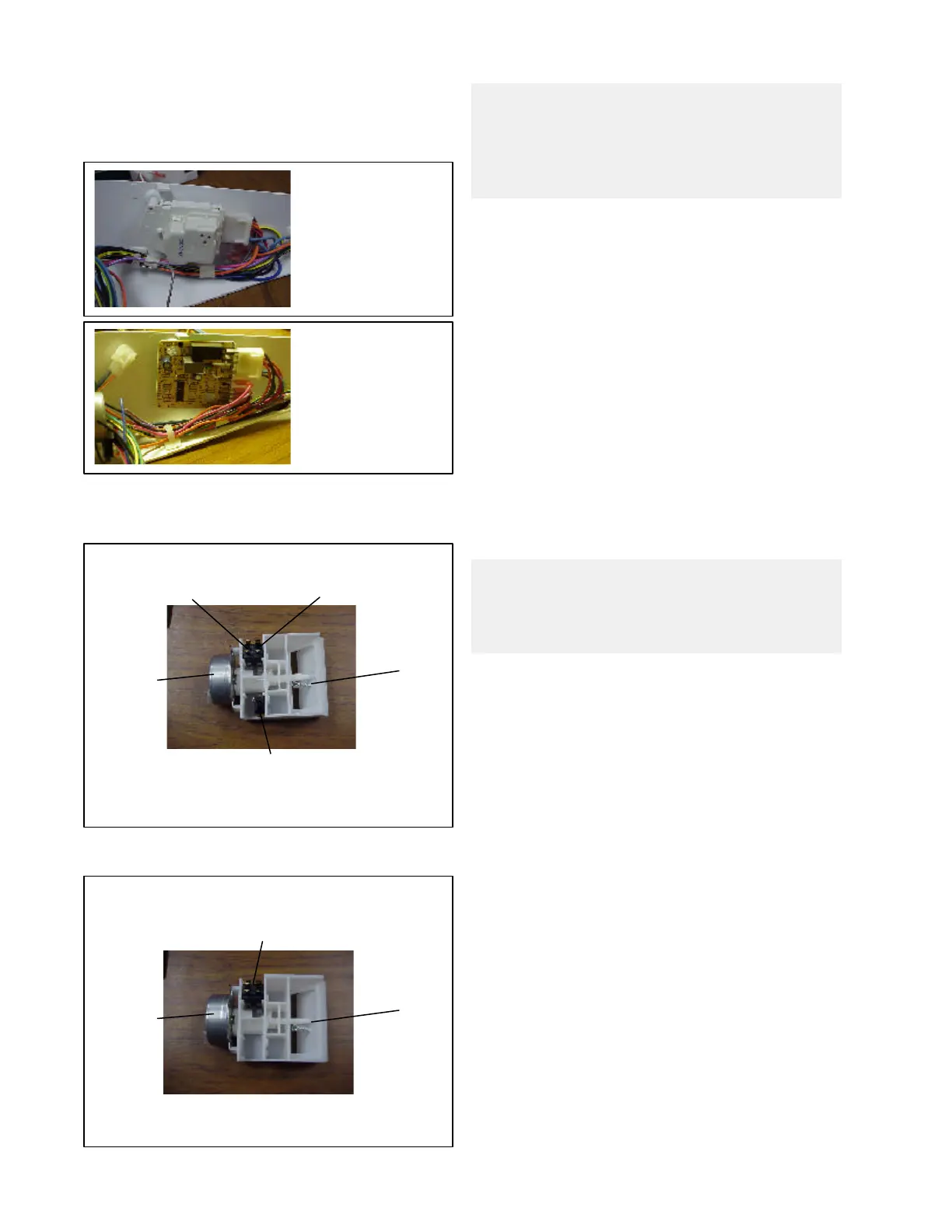
Figure 23
Damper Control for ADC Models
Damper Motor Switches
(Top Switches)
Damper
Motor
Damper
Figure 20
Figure 21
On models with an ADC, the evaporator fan is controlled
by the defrost control. (See Figure 23.)
The mechanical timer is a standard 8 hour timer that will
shut off the compressor and allow the refrigerator to go
into defrost. On 115 volt units, the timer motor will only
advance when the compressor is running. On 220 volt
units, the timer motor will run continuously. In either
case, when the timer motor has run for 8 hours, the
compressor will shut off and the unit will go into defrost.
On mechanical timer models, the two switches closest
to the damper are connected to the damper motor. The
bottom switch is connected to the freezer fan motor. When
the food compartment control is in the OFF position and
the damper is closed all the way, the fan motor is
connected to the freezer control by the bottom switch.
(See Figure 18.)
When the food compartment control is in the ON position
and the damper is open all the way, the fan motor is
connected to the food compartment control and the fan
will start running. (See Figure 19.)
The fan can be activated by either the food compartment
control or the freezer compartment control. If the food
compartment is calling for cooling and the fan is running,
then if the freezer control contacts close, the compressor
and the condenser fan motor will start. Once the food
compartment control is satisfied, the damper will close.
This will connect the fan motor to the freezer control.
The fan motor will continue to run until the freezer control
is satisfied and the unit shuts off. This is accomplished
by the switch closest to the motor. (See Figure 22.) When
the damper is open, the fan is connected to the food
compartment control.
On models with an ADC, the top two switches are
connected to the damper and there is no bottom switch.
(See Figure 23.)
ADAPTIVE DEFROST CONTROL (ADC)
Electrical Requirements
Input Voltage:
• Voltage between L1 (E8 on the board) and Neutral
(E4 on the board) connectors on the PC board shall
be LINE VOLTAGE ± 10%.
• The freezer cold control (E2) supplies line voltage to
the ADC relay center contact to run the compressor
and condenser fan motor, as well as the defrost
Note: Defrost interval timing is based on accumu-
lated compressor run time for all 115 volt units, and
is based on elapsed clock time for all 220 volt units,
whether a mechanical timer or ADC is used.
NOTE: On mechanical timer models, the evapora-
tor fan motor will not start running until the defrost
terminator switch resets. (See Figures 18 and 19.)
 Loading...