ControlWave Instruction Manual (CI-ControlWave)
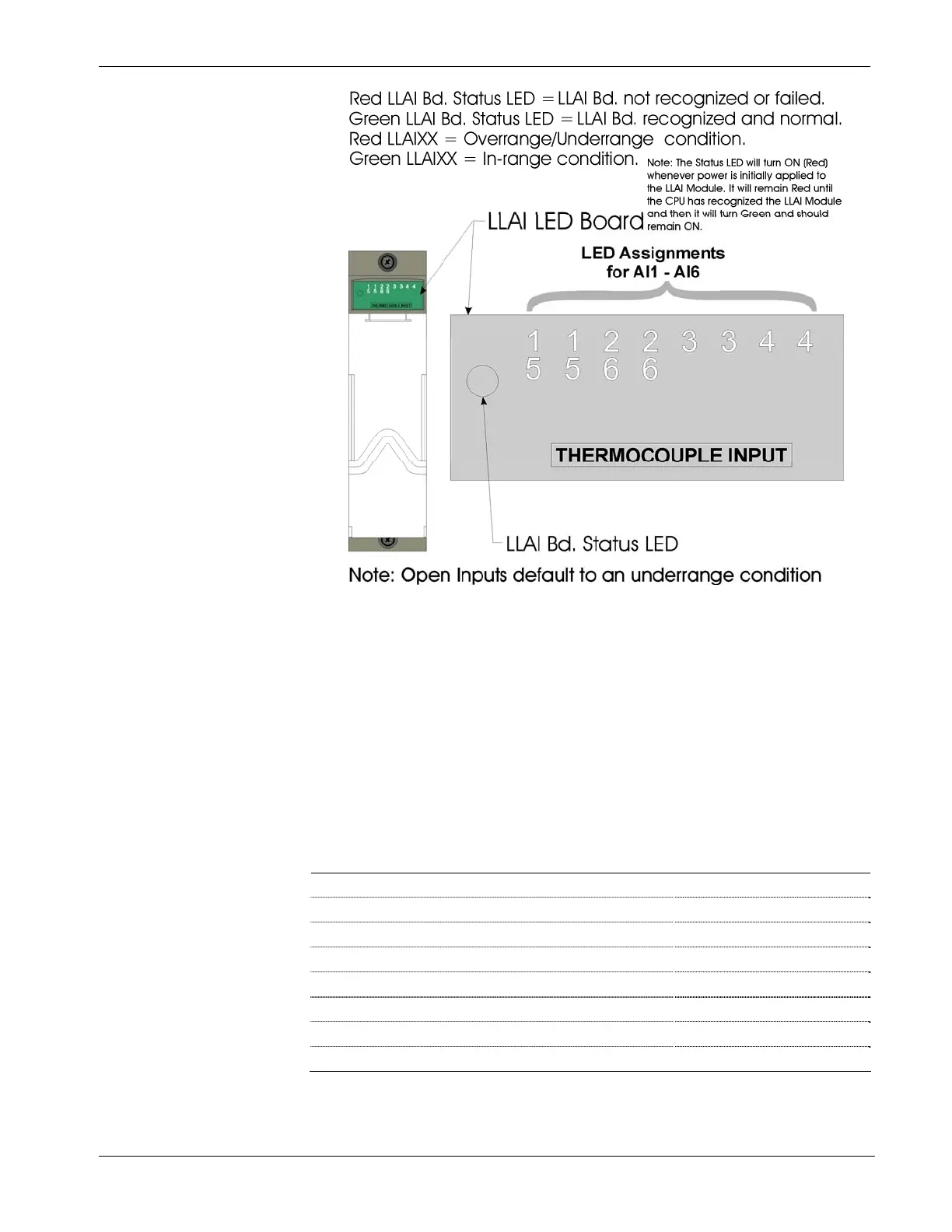
Figure 5-18. Low Level Analog Input (LLAI) Module LED Designations
5.3.2 Checking Wiring/Signals
Check I/O field wiring at the terminal blocks and at the field device.
Inspect the wiring for continuity, shorts, and opens. Check I/O signals at
their respective terminal blocks (see Table 5-2).
Table 5-2. I/O Field Wiring - Terminal Block Reference
I/O Module or sub-system Notes
Digital Input Modules See Section 3.4
Digital Output Modules See Section 3.5
Analog Input Modules See Section 3.6
Analog Output Modules See Section 3.7
Universal Digital Input (UDI) Modules See Section 3.8
RTD Input Modules See Section 3.9
Low Level Analog Input Modules See Section 3.10
Watchdog Circuit See Section 2.3.5
Revised Nov-2010 Service & Troubleshooting 5-21

 Loading...


