ControlWave Instruction Manual (CI-ControlWave)
3.4 Digital Input (DI) Modules
DI modules provide 16 or 32 digital inputs. Using jumpers, you can
individually configure each input as either externally sourced or
internally powered using an internal +21Vdc power supply (dry
contacts).
Note: Early versions of ControlWave DI modules required you to
specify either internal or external sourcing for all DIs when you
ordered the module; now you can set this yourself using jumpers
on a per DI basis.
Table 3-1 DI Module General Characteristics
Type Number
Supported
Characteristics
Digital Inputs (DI)
16 or 32
Each DI supports/ includes:
Nominal input voltage of 24Vdc at 5
mA.
Jumper to configure choice of either:
externally sourced input - or -internally
powered dry contact using internal
+21 Vdc power supply.
Nominal input current of 5 mA
30 ms input filtering
Dedicated LED on module turns ON
when DI is ON
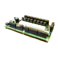
A DI module consists of a digital input printed circuit board (PCB) with
either a terminal block assembly (for local termination) or a header
block assembly (for remote termination). Each DI module also includes
an LED board, as well as I/O assembly and mounting hardware. The DI
PCB connects to the backplane using a 110-pin connector.
Detailed Technical
Specifications
For detailed technical specifications, please see document CWPAC
available on our website http://www.emersonprocess.com/remote.
Configurations
DI modules (general part number 396357-XX-X) come in several
different configurations. See Table 3-2 to see the variations.
Table 3-2 DI Module Configurations
Part Number Number of DIs Termination Connector
396357-01-6 32
Local
396357-02-4 16 Local
396357-11-3: 32 Remote
396357-12-1 16 Remote
Isolation
Surge suppressors and optocouplers electrically isolate the DI field
circuitry from the module’s bus interface circuitry. Inputs configured
3-8 I/O Modules Revised Nov-2010
 Loading...

