ControlWave Instruction Manual (CI-ControlWave)
Revised Nov-2010 I/O Modules 3-33
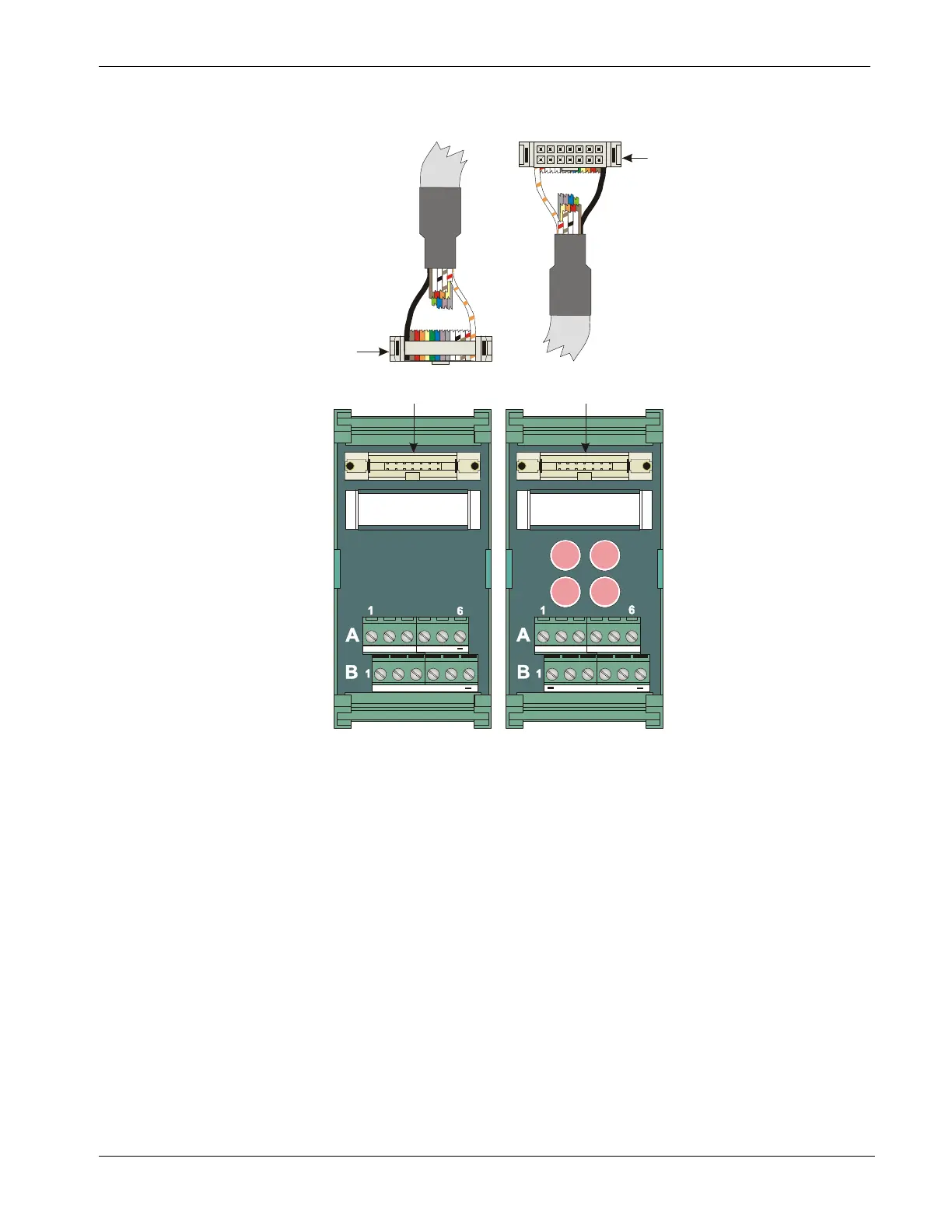
12/24V UDI
(with fuses)
12/24V UDI
(without fuses)
+
.7
.2 .4 .6
.1
.3 .5
.0
+
+
7
24 6
1
35
0
+
From P1
From P2
A = Top TB
able Assembly
(One of 2 Cables)
End of cable that interfaces with
Remote UDI Module’s
Header Block Assembly
End of cable that interfaces with
Remote UDI Module’s
DIN-Rail Mountable
Terminal Block Assembly
UDI1 - UDI3
UDI4 - UDI6
A = Top TB
= N/A
= UDISET1
= UDIRST1
= UDICOM2
= UDISET3
= UDIRST3
B = Bottom TB
+
.0
.2
.4
.6
_
+
.1
.3
.5
.7
= N/A
= UDICOM1
= UDISET2
= UDIRST2
= UDICOM3
= UDIRST3
_
= N/A
= UDISET4
= UDIRST4
= UDICOM5
= UDISET6
= N/A
B = Bottom TB
+
0
2
4
6
+
1
3
5
7
= UDIRST6
= UDICOM4
= UDISET5
= UDIRST5
= UDICOM6
= UDIRST6
_
FUSE
F0
FUSE
F2
FUSE
F4
FUSE
F6
_
FUSES: F0, F2, F4, F6: 1/8A
Figure 3-28. Remote DIN-Rail Mountable Terminal Block Assembly Assignments for UDI Operation

 Loading...


