ControlWave Instruction Manual (CI-ControlWave)
Revised Nov-2010 I/O Modules 3-5
module’s removable terminal blocks) or “remote termination” (field
wiring connected to the remote headers under the module’s cover and
routed to a DIN-rail mounted terminal assembly and then to field
devices).
ControlWave I/O modules use compression-type terminals that
accommodate up to #14 AWG wire. Insert the wire’s bared end (approx.
¼” max) into the clamp beneath the screw and secure the wire. To
prevent shorts, ensure that no bare wire is exposed. If using standard
wire, tin the bare end with solder to prevent flattening and improve
conductivity. Allow some slack in the wires when making terminal
connections. Slack makes the wires more manageable and helps
minimize mechanical strain on the terminal blocks.
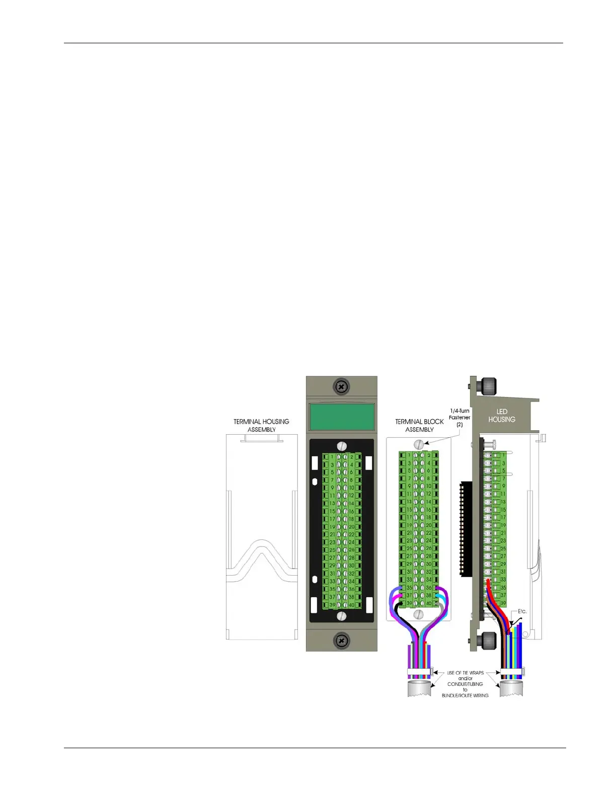
3.2.1 Local Termination
For I/O modules equipped with local terminal blocks, install the field
wiring between the I/O module’s removable terminal block connectors
and field devices (see Figure 3-3). Use AWG 14 or smaller wire
(consult with the field device manufacturer for recommendations).
Leave some slack and plan for wire routing, identification, and
maintenance. Route the bundled wires out through the bottom of the I/O
module assembly between the terminal block and the terminal housing.
Figure 3-3. I/O Module (Local Termination) Wire Routing

 Loading...


