ControlWave Instruction Manual (CI-ControlWave)
2-4 Installation Revised Nov-2010
2.2.2 Color Coding of Slot Connectors
A color tab on each backplane connector matches the color on the
module which you can place in that slot.
PSSM goes in the first slot (Yellow tab)
CPU goes in the second slot (Blue tab)
I/O modules go in any other slot (Green tab)
2.2.3 Mounting the Housing
You can install a ControlWave equipped with a 4-I/O module housing
on a wall or panel. See Figure 2-2 for mounting hole patterns for a 4-
I/O unit.
You can install a ControlW
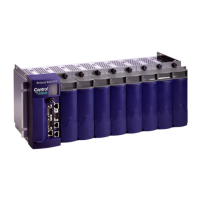
ave equipped with an 8-I/O module housing
in a 19-inch equipment rack, a panel or a wall. These units ship from the
factory with the end plates configured for 19-inch rack mounting.
Remove the end plates, rotate them 180° and then reinstall them to
accommodate panel or wall mounting. See Figure 2-1 for hole patterns
and dimensions.
When you install any of these units on a panel or wall, position it
according to the following restrictions:
Position the unit so that you can see the front of the assembly and so
it is accessible for service such as installing a module or replacing a
battery.
Do not install ControlWave modules until you mount the housing
and ground it properly.
 Loading...

