ControlWave Instruction Manual (CI-ControlWave)
10/100Base-T connectors.
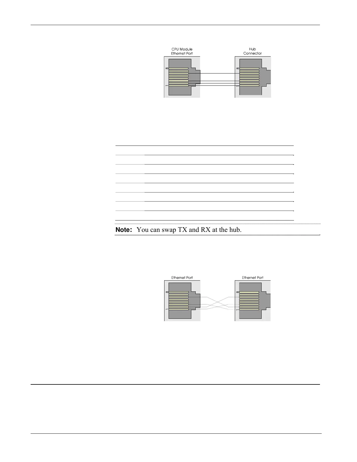
Figure 2-17. Standard 10/100Base-T Ethernet Cable (CPU Module to Hub)
Table 2-14. Ethernet 10/100Base-T CPU Module Pin Assignments
Pin Description
1 Transmit Data+ (Output)
2 Transmit Data– (Output)
3 Receive Data+ (Input)
4 Not connected
5 Not connected
6 Receive Data– (Input)
7 Not connected
8 Not connected
Note: You can swap TX and RX at the hub.
You can connect two nodes in a point-to-point configuration without
using a hub. However, you must configure the cable so that the TX+/-
Data pins connect to the RX+/- Data pins (swapped) at the opposite
ends of the cable (see Figure 2-18).
Figure 2-18. Point-to-Point 10/100Base T Ethernet Cable
The maximum length of one segment (CPU to hub) is 100 meters (328
feet). The use of Category 5 shielded cable is recommended.
2.5 Bezels
The bezel is a blue plastic cover (see Figure 2-19) that protects the CPU
and PSSM modules. Another function of the bezel is to let you route
bundled wires and cables downward between the modules and the bezel.
The factory ships a version of the bezel appropriate to the options you
ordered.
2-30 Installation Revised Nov-2010

 Loading...


