ControlWave Instruction Manual (CI-ControlWave)
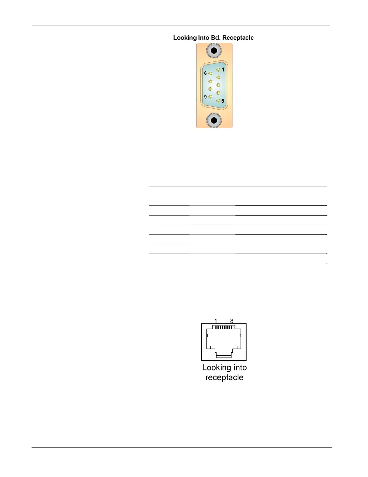
Figure 2-10. Male DB9 9-Pin Connector
Table 2-7. COM1 & COM2 RS-232 Port Connector Pin Assignment
Pin
RS-232
Signal
RS-232 Description
1 DCD Data Carrier Detect Input
2 RXD Receive Data Input
3 TXD Transmit Data Output
4 DTR Data Terminal Ready Output
5 GND Signal/Power Ground
6 DSR Data Set Ready Input
7 RTS Request to Send Output
8 CTS Clear to Send Input
9 RI Ring Indicator
Figure 2-11 shows the RJ-45 connector used for COM3 on the SCB. If
you ordered COM3 as an RS-232 port, see Table 2-8 for pin
assignments.
Figure 2-11. RJ-45 Connector Associated with COM3 (SCB)
2-24 Installation Revised Nov-2010

 Loading...


