Redundant Power Supply Sequencer Module (RPSSM)
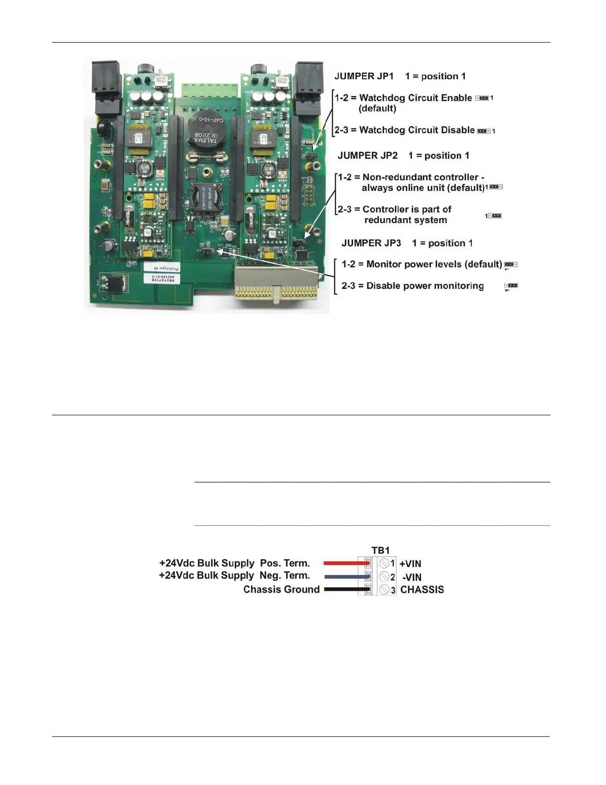
Figure P-3. Jumper Locations
Make the necessary adjustments to the jumpers according to Table P-1.
When finished, re-attach the case by first aligning the protective case with
the screw holes, then inserting and tightening each screw.
Wiring Power Connections
Use terminal blocks TB1 and TB2 to connect an external bulk power
supply to the RPSSM. An external 24V power supply (22.2 to 30V)
connected to TB1 provides system power to the ControlWave including
the CPU boards and I/O boards (see Figure P-4).
Note
: Be sure you route wires to the terminal block connectors so they
do not interfere with removal/replacement of the power supply
modules.
Figure P-4. Wiring System Power to the RPSSM
An external power supply (22.2 to 30V) connected to TB2 provides field
power to I/O boards, and any field devices (switches, relays, etc.)
powered through the I/O boards (see Figure P-5).
P-4 Installation and Use Revised Nov-2010

 Loading...


