Redundant Power Supply Sequencer Module (RPSSM)
Figure P-5. Wiring Field Power to the RPSSM
Wiring Watchdog Circuitry and Redundancy Connections
When the CPU’s hardware detects improper software operation, it
triggers a watchdog condition. If you have enabled the watchdog
hardware using jumper JP1, the watchdog condition triggers a failure to
the redundant unit and resets the CPU.
The circuit that drives the watchdog switch is on the secondary side of the
power supply. A solid state relay actuates the watchdog hardware and is
factory enabled or disabled via jumper JP1 (see Setting Jumpers).
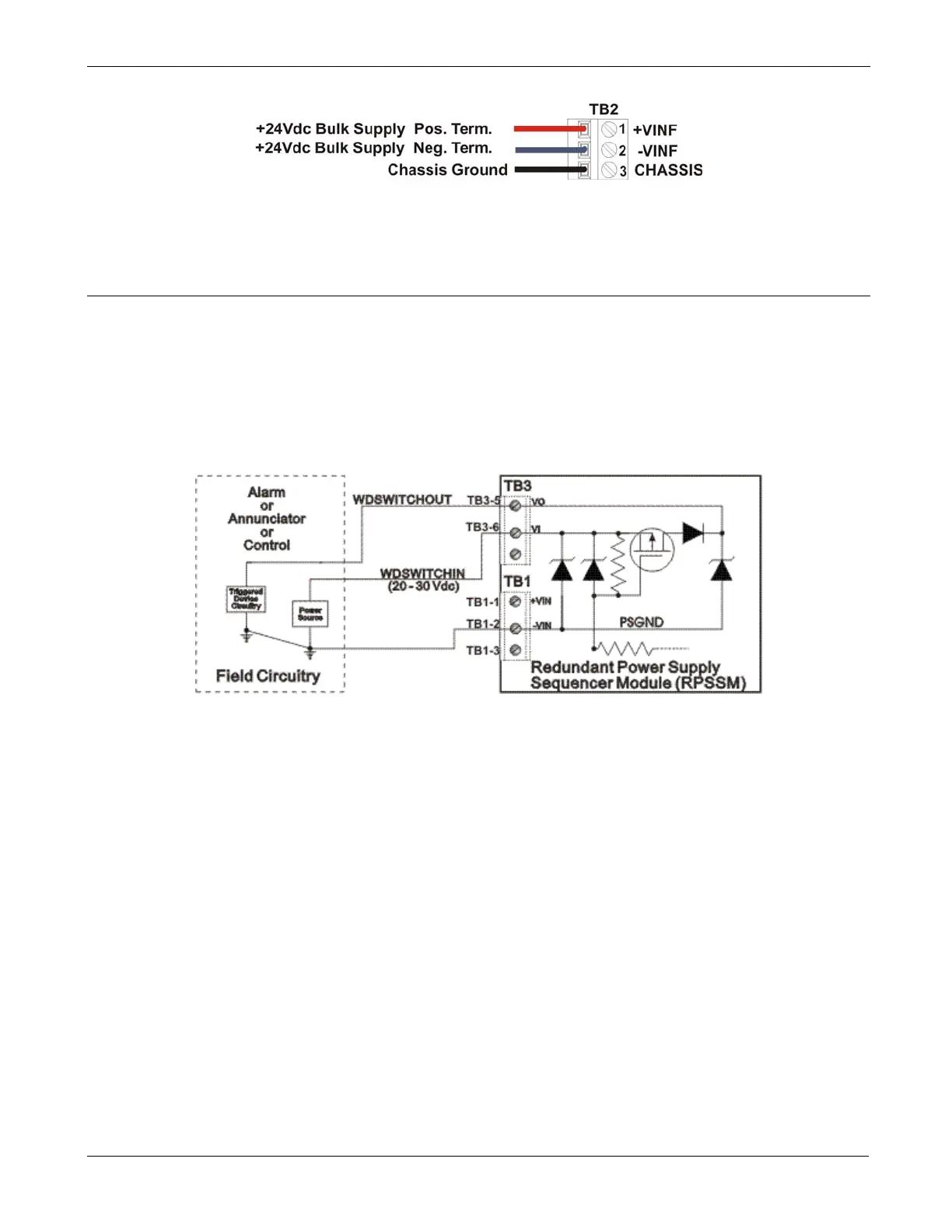
Figure P-6. Watchdog Switch Field Wiring
The VI input of the terminal block (TB3-6) powers the watchdog switch.
Its switched output connects to the VO output of the terminal block (TB3-
5). Reference the external power source connected to the VI terminal to
the return point of the input source that powers the RPSSM [-VIN (TB1-
2)].
RPSSM connector TB3 provides watchdog switch and redundancy
control connections as follows:
Connections
TB3-5 = VO - Watchdog switch output
TB3-6 = VI - Watchdog switch input
TB3-7 = VR - Redundant unit control input (Used with ControlWave
RED I/O)
When using a pair of ControlWave I/O expansion racks, each with an
RPSSM, and a ControlWave Redundant I/O and Communications Switch
Unit (the redundant I/O switcher), the choice of which unit is “online”
and which unit is “backup” is determined by redundancy control line
Revised Nov-2010 Installation and Use P-5

 Loading...


