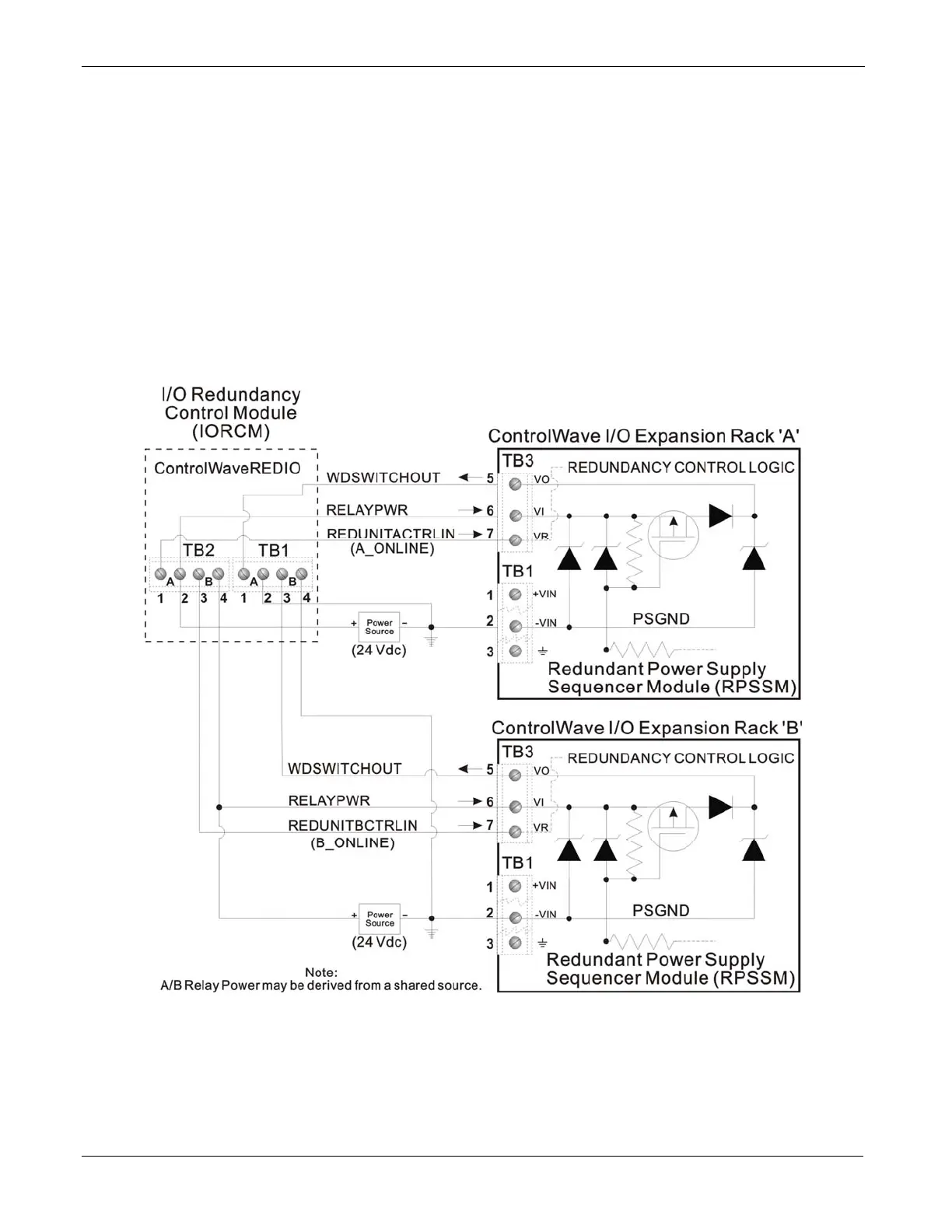
Redundant Power Supply Sequencer Module (RPSSM)
wiring between the ControlWave I/O redundancy control module
(IORCM) on the I/O switcher, and each I/O expansion rack (See
FigureP-7).
Wire terminal block connector TB3-7 on the “A” I/O expansion rack
RPSSM to TB2-1 on the IORCM, and TB2-2 on the IORCOM to 24V.
Similarly, wire terminal block connector TB3-7 on the “B” I/O expansion
rack RPSSM to TB2-3 on the IORCM, and TB2-4 on the IORCOM must
to 24V.
Figure P-8 shows the location of the IORCM connectors on the
ControlWave I/O Switcher.
Figure P-7. – ControlWave to ControlWave REDI/O - Redundancy Field Wiring
P-6 Installation and Use Revised Nov-2010

 Loading...


